


7
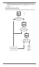
Procedure 2: Install the Adapter Cable
Two digital inputs located on the adapter cable are available to monitor
the on/off state of lights, including brake lights, or of other 12 VDC
electrical accessories. Typically Digital Input 1 monitors the brake
lights and Digital Input 2 monitors the headlights. In the DriveRight
software Digital Input 1 is recorded in the GPS table and in the acci-
dent logs. Digital Input 2 is only recorded in the GPS table.
You can record the digital input status during a trip by enabling GPS in
DriveRight FMS, even if you aren’t using the optional GPS module.
CAUTION: Connecting the digital inputs can be hazardous to both the installer and
your vehicle’s electrical system if not done by an experienced installer.
This manual assumes you are aware of the inherent dangers of working in
and around a vehicle and have a working understanding of electricity.
1. If you are not using the digital inputs go to Step 6 of this procedure.
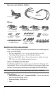
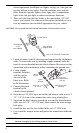
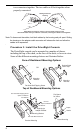
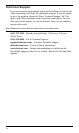
2. Use an in-line splice to con-
nect the red +12 VDC wire
from the adapter cable to the
red +12 VDC wire in the har-
ness cable. Be sure the tap is
protected by the harness cable
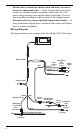
fuse. Refer to the “Wiring
Diagram” on page 4.
3. Connect the black ground
wire from the adapter cable to chassis ground.
4. Use in-line butt splices to connect the blue wires with fuses to the
green and yellow digital input cables.
5. Use the included T-Tap disconnects to connect Digital Inputs 1 and
2 to the desired circuits.
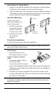
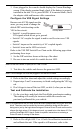
6. Connect the adapter cable to the harness cable.
It is easiest to make the connection by first holding the harness
cable connector by the housing. Then hold the adapter connector on
the cable itself next to the sliding connector housing and push the
In-Line Splice
Trim off flush
stripped wire
Red +12VDC
Harness Cable
Wire
Red +12VDC
Adapter Cable Wire