4
• Decide where to install the harness cable and where to connect
the power and ground leads — Find a location inside the vehicle
where you can bring together the harness cable leads, the VSS,
power and ground tap wires and the adapter cable leads. The loca-
tion must allow the adapter cable to reach the DriveRight console.
• Determine where to connect the digital input leads (if used) — In
many installations Digital Input 1 monitors brake lights and Digital
Input 2 monitors headlights.
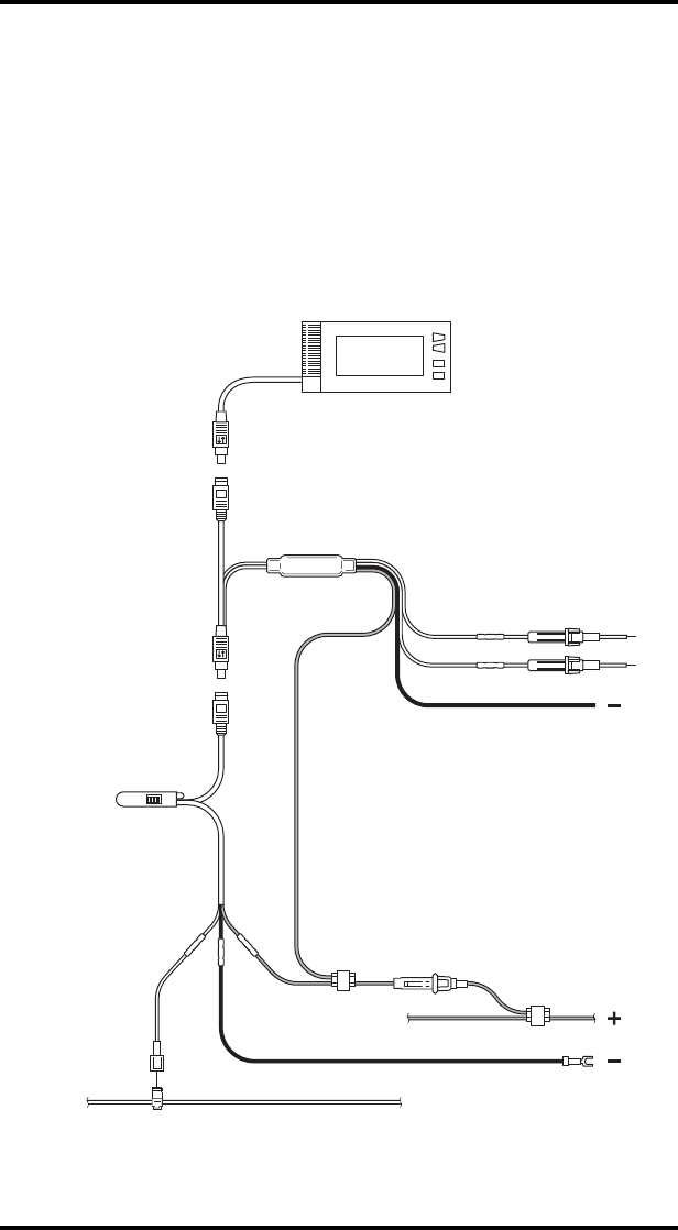
Wiring Diagram
The diagram below is an example of the DriveRight 600
E VSS wiring.
DriveRight 600E Console
Harness Cable
Adapter Cable
RedWhite
Male
Disconnect
Butt Splices (3)
Red Wire with
Fuseholder
In-Line
Splice
In-Line
Splice
Butt
Splices
(2)
Blue Wires
with
In-Line
Fuses
Green
Yellow
Red
Red
Black
Black
T-Tap
Connector
Unswitched
+12V
Ground
Ground
Spade
Terminal
Vehicle Speed Sensor Wire
VSS
White Wire
(if needed)
Digital
Inputs
1
2


