


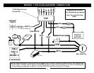

WIRING
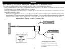
PIN 6: GRAY: (-) NEGATIVE HOOD PIN SWITCH (REQUIRED FOR PROGRAMMING)
Connect the Gray wire to a switch that is at ground when the hood is open. If an existing switch is not available, then we
recommend installing the supplied pin switch. When this wire is grounded, (hood is open) remote starting is inhibited.
The hood pin is also required for option and remote transmitter programming. If installing the supplied pin switch, find a
location around the perimeter of the engine compartment. Do not mount pin switch in water pathways. A small Brown
wire is included in the kit for use when connecting the hood pin switch.
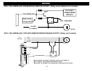
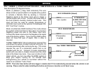
PIN 5: PINK: NEGATIVE or POSITIVE DIESEL GLOW PLUG INPUT
Connect Pink wire to indicator circuit that shows a (- or +) Signal while the “WAIT TO START LAMP” is on. When this
wire is used, the system will wait until light turns off before attempting a remote start. Note: This input is jumper
selectable for Positive or Negative type signals. See jumper pin diagram on page 23 for configuration.
PIN 4: PURPLE: (+12V) BRAKE RESET
Connect the Purple wire to the side of brake pedal switch that shows +12 volts ONLY when pedal is depressed. This is
the wire that turns off the remote start once the driver’s key is in the Ignition and turned to the ON position.
PIN 3: ORANGE/BLACK: (-) OEM DISARM OUTPUT
This wire provides a Ground pulse to disarm the vehicles' Factory anti-theft system prior to a Remote Start. Connect this
wire to the vehicles' anti-theft disarm wire. This wire is sometimes found coming off the Driver's door key switch or at the
Factory Anti-theft control module. This wire may not be needed if Factory Security only requires a door unlock pulse.
PIN 2: ORANGE: (-) OEM REARM OUTPUT
This wire provides a ground pulse to rearm the vehicles' FACTORY anti-theft system after a timed-out or aborted remote
start. Connect this wire to the vehicles' anti-theft rearm wire or to the door pin circuit depending on your requirements.
This wire may be needed to pulse the door pin circuit on vehicles with retained accessory power.
PIN 1: RED/WHITE: TACHOMETER INPUT
When installing this system Tach mode, this wire must be connected to a valid source of AC voltage. This wire allows
the unit to sense the engine running and control the starter motor. See TACH REFERENCE MODE section.
PROGRAM/OVERRIDE SWITCH: 2 PIN PLUG (REQUIRED FOR PROGRAMMING & LEARNING REMOTES)
This switch is used for programming features, transmitters, valet mode, and to override the optional starter disable (if installed) in
the event of a non-operating remote control.
LED: 2 PIN PLUG (OPTIONAL)
The LED is used as a VALET/PROGRAMMING indicator and it will also FLASH for use as security deterrent when the optional
ANTI-GRIND/STARTER DISABLE output is programmed.
7