


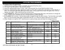
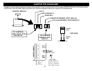
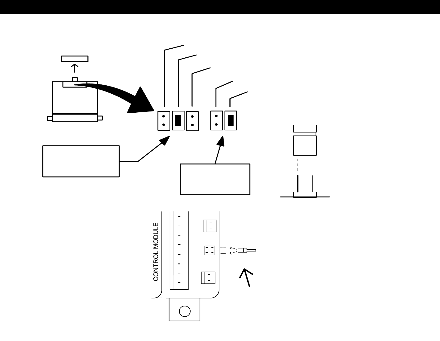
JUMPER PIN DIAGRAMS
Jumper pins are used to change/configure the operation of the on board multi-function output PINK/WHITE wire, the Parking Light
WHITE wire and the PINK glow plug input wire. See the diagrams below for Jumper Pin configurations.
JUMPER
PLUG
SIDE VIEW
JUMPER
PINS
JP1 JUMPERS:
IGN 2 (DEFAULT)
ACC 2
(-) NEGATIVE PARKING LIGHT (500 mA)
+12V (10A) PARKING LIGHT (DEFAULT)
IGN2 / ACC2 / STR2
PINK WHITE
JP2 JUMPERS:
PARKING LIGHT
OUTPUT
CONTROL MODULE
STARTER 2
GLOW PLUG
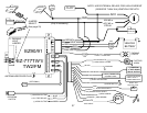
PINK WIRE:
Jumper Select for
Postive or Negative
Type "Wait" Circuits
25