


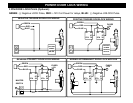
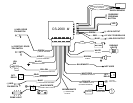

WIRING
BROWN/WHITE WIRE: (-) HORN PULSE / CHIRP OUTPUT (Optional, may require a relay)
Connect to the Negative Horn Trigger wire usually located near the steering column. If the vehicle horn circuit
requires +12V, then a relay is required. RELAY WIRING: Connect the Brown/White wire to terminal 85,
connect relay terminals 86 and 87 to +12V constant power. Connect terminal 30 of the relay to the +12V
positive device/circuit to be activated.
ORANGE WIRE: (-) NEGATIVE ARMED OUTPUT / STARTER DISABLE (500mA Ground, Optional)
This wire becomes a (-) Ground output when system is armed. This output is used for disabling the starter or
to activate optional devices such as extra sensors, LED’s, window roll-up modules, voice modules etc. For
starter kill, cut starter wire and connect between 87A and 30 on relay. Connect orange wire to 85 and connect
86 to an Ignition source that has voltage in the ON and CRANKING position. (See wiring diagram for relay
configuration-Pg. 16)
WHITE/RED WIRE: (-) AUX REMOTE OUTPUT 2 (Optional, may require a relay)
This wire connects the same way as Remote Output 1 see GRAY WIRE last page.
BLUE/WHITE WIRE: NOT USED / NO CONNECTION
BROWN WIRE: (+) SIREN OUTPUT (3 Amp Max.)
Connect to RED siren wire from the Siren in the engine compartment.
WHITE WIRE: +12V FLASHING PARKING LIGHT OUTPUT
Connect to the switched parking light wire at back of light switch. If this is not possible, connect directly to one
of the parking lights at the front of the vehicle. European vehicles require separate right and left circuits. Use
a dual relay or 2 diodes to separate the output signal.
RED WIRE: +12V POWER INPUT (15 amp fuse)
Connect to +12 Volt source with supplied fuse & holder. Recommended location for this connection is at the
vehicle battery positive terminal.
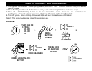
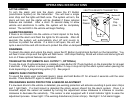
SHOCK SENSOR: The sensor supplied with
this system does not require any additional
wiring. Simply mount the sensor in a suitable
location, plug it in, and adjust sensitivity.
2 PIN PLUG (BLUE): PROGRAM/OVERRIDE PUSH-BUTTON
2 PIN PLUG (RED): LED INDICATOR (RED FLASHING LIGHT)
4 PIN SENSOR PLUG: WHITE Wire: Negative Pre-Warning,
BLUE Wire: Negative Trigger, BLACK Wire: Sensor
Ground, RED Wire Sensor +12V Power