


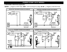
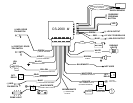

WIRING
GREEN WIRE: (-) DOOR TRIGGER
Identify the wire that reads ground when any door is open and 12 volts when all doors are closed. Some
vehicles may have isolated door triggers. In this case you may need to run additional wires from other doors
or go directly to the wire that triggers the vehicle’s interior dome light. One vehicle will not require the use of
BOTH door trigger wires.
VIOLET WIRE: (+) DOOR TRIGGER
Same as the GREEN wire above except this wire is used for vehicles that show a positive voltage (12 volts)
when the door is open and a ground when doors are closed as in many Ford, Lincoln, and Mercury vehicles.
BLACK WIRE: SYSTEM CHASSIS GROUND
The Black wire MUST be connected the CHASSIS METAL of the vehicle. Scrape away any paint or debris
from the connection point and use a star washer to ensure a good connection. Keep the ground wire short.
YELLOW WIRE: IGNITION SWITCHED “ON” AND “START” +12 VOLTS
Connect to an IGNITION wire (or fuse in the fuse box) that shows +12 Volts when the key in both “On” and
“Start” (WHEN CRANKING) positions.
GRAY WIRE: (-) AUX REMOTE OUTPUT 1 (Optional, may require a relay)
Connect to the Negative trunk release circuit or to the activation circuit of an auxiliary module or device. If the
circuit requires +12V, then a relay is required. RELAY WIRING: Connect the Gray wire to terminal 85, connect
relay terminals 86 and 87 to +12V constant power. Connect terminal 30 of the relay to the +12V positive
device/circuit to be activated.
BLUE WIRE: (-) HOOD/TRUNK TRIGGER (Optional)
Input trigger for a grounding hood or trunk pin switch. Connect to existing hood and trunk pin switches that
read ground when open. If no existing switches are available, install new pin switches if desired. Note: DO
NOT mount new pin switches in water pathways.
BLACK/WHITE WIRE: (-) DOME LIGHT ILLUMINATION OUTPUT (Optional, may require a relay)
Negative Dome Light System: Connect directly to dome light activation circuit.
Positive Dome Light System: Connects to terminal 85 of a relay. Connect terminals 86 & 87 to +12V
Constant. Connect terminal 30 to the dome light activation circuit.
NOTE: A relay may still be required on Negative Dome Light Systems if there are many dome lights to turn
on. (Minivans, SUV’s & Luxury vehicles) Follow the relay wiring steps for positive, but connect terminal 87 to
Ground.