frame, and remove rear engine frame-to-body mounting bolts. Ensure
rear of engine frame can be lowered without damaging other components.
Separate steering coupler from rack and pinion. On Eldorado, remove
transaxle mount. Using jack, lower rear end of engine frame.
4) Place a drain pan under rack and pinion. Remove power
steering pressure and return lines from rack and pinion assembly.
Remove rack and pinion mounting bolts and bushings. Remove rack and
pinion from vehicle through left wheel opening on most models.
Installation
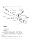
To install, reverse removal procedures. Tighten nuts and
bolts to specifications. Apply Loctite to threads and tighten in
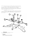
sequence. See Fig. 3. See TORQUE SPECIFICATIONS. Fill and bleed
hydraulic system. See HYDRAULIC SYSTEM BLEEDING under LUBRICATION.
Adjust toe-in as necessary. See appropriate SPECIFICATIONS &
PROCEDURES article in WHEEL ALIGNMENT.
Removal ( "E" Body)
1) Disconnect battery. Raise and support vehicle. Remove
front wheels. Remove power steering pressure hoses from rack and
pinion. Separate outer tie rod ends. See OUTER TIE ROD. Remove
steering column-to-rack coupler pinch bolt.
2) Support front suspension crossmember with a suitable jack.
Remove brake pipes from the retainers on the front suspension support.
Remove front suspension crossmember mounting bolts. Lower front
suspension crossmember in order to remove rack and pinion. Remove rack
and pinion mounting bolts. Remove rack and pinion from front
suspension crossmember.
Installation
To install, reverse removal procedures. Tighten nuts and
bolts to specifications. Apply Loctite to threads and tighten in
sequence. See TORQUE SPECIFICATIONS. Fill and bleed hydraulic system.
See HYDRAULIC SYSTEM BLEEDING under LUBRICATION. Adjust toe-in as
necessary. See appropriate SPECIFICATIONS & PROCEDURES article in
WHEEL ALIGNMENT.
Removal ("F" Body)
1) Disconnect negative battery cable. Remove serpentine belt,
(if needed). On (V8), remove air intake resonator. On all models,
place drain pan under vehicle and drain power steering fluid. Raise
and support vehicle. Remove front wheels. Support engine with suitable
jack. Disconnect power steering pressure and return hoses from rack
and pinion assembly.
2) Remove steering coupler pinch bolts and remove coupler
from rack and pinion. Disconnect and separate front tie rod ends. See
OUTER TIE ROD. On (V8), remove generator. On (V8), remove left-side
engine mount through-bolt. On all models, remove rack and pinion
mounting bolts and nuts. Remove rack and pinion.
Installation
To install, reverse removal procedures. Tighten nuts and
bolts to specification. See TORQUE SPECIFICATIONS. Fill and bleed
hydraulic system. See HYDRAULIC SYSTEM BLEEDING under lubrication.
Adjust toe-in as necessary. See appropriate SPECIFICATIONS &
PROCEDURES article in WHEEL ALIGNMENT.
Removal ("Y" Body)
1) Disconnect negative battery cable. Remove brake pressure
modulator valve (BPMV) bracket. Place drain pan under vehicle and
drain P/S fluid. Remove intermediate shaft shield. Disconnect power
steering pressure and return hoses from rack and pinion assembly.
Disconnect power steering cooler and remove from vehicle. Remove


