


of turns required for removal. Remove hex jam nut from inner tie rod.
Remove adjusting nut from inner tie rod. Remove outer boot clamp. Cut
off and discard inner boot clamp. Mark location of breather tube (if
equipped) for reassembly reference. Slide boot from inner tie rod.
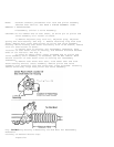
2) Slide shock damper ring on inner tie rod assembly back
toward rack. Place a wrench on flat side of rack to prevent turning.
Place another wrench on flats of inner tie rod. Rotate inner tie rod
counterclockwise until it separates from piston and rack. On "C", "F",
"N" and "Y" bodies, clean old Loctite from threads of rack and inner
tie rod. Remove shock damper ring.
Reassembly
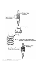
1) Install shock damper ring. To prevent internal damage,
hold rack with a backup wrench during tie rod installation. Apply
Loctite No. 262 to inner tie rod threads. Install inner tie rod onto
rack. Tighten inner tie rod to specification. See
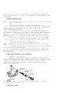
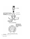
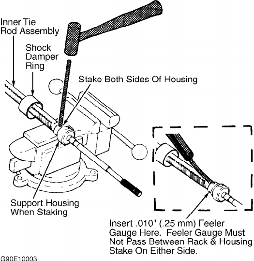
TORQUE SPECIFICATIONS. Stake tie rod fittings as shown in
illustration. See Fig. 11.
2) Ensure inner tie rod pivots freely in all directions, and
then stake both sides of inner tie rod to flats on rack. See Fig. 11.
Ensure both stakes are okay by inserting a .010" (.25 mm) feeler gauge
between rack and tie rod housing. Feeler gauge must not pass between
rack and housing stakes.
3) To complete reassembly, reverse disassembly procedure.
Apply grease to inner tie rod and housing before installing boots.
Install outer tie rod end with same number of turns as when removed.
Install new cotter pin at castle nut. DO NOT back off castle nut to
install cotter pin. Adjust toe-in as necessary. See appropriate
SPECIFICATIONS & PROCEDURES article in WHEEL ALIGNMENT. Fill and bleed
hydraulic system. See HYDRAULIC SYSTEM BLEEDING under LUBRICATION.
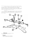
Fig. 11: Staking & Inspecting Inner Tie Rod
Courtesy of General Motors Corp.
TORQUE SPECIFICATIONS