


NOTE: Perform overhaul procedures with rack and pinion assembly
removed from vehicle. See RACK & PINION ASSEMBLY under
REMOVAL & INSTALLATION.
Disassembly (Pinion & Valve Assembly)
CAUTION: Do not hammer end of stub shaft, as drive pin on pinion and
valve assembly will loosen or break.
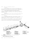
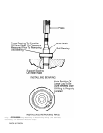
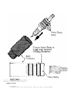
1) Remove adjuster plug lock nut, adjuster plug, adjuster
spring and rack bearing. See Fig. 1. Remove retaining ring from stub
shaft. Remove dust cover from bottom of pinion and valve assembly
housing. While holding stub shaft stationary with 14-mm wrench, remove
lock nut from bottom of shaft.
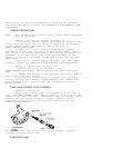
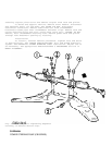
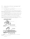
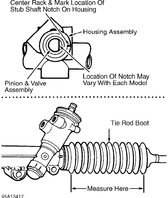
2) Center rack in housing. For reassembly reference, mark
location of stub shaft notch on housing, and measure distance between
ends of tie rod boot. See Fig. 8.
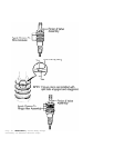
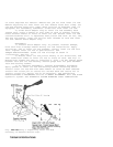
3) Using an arbor press, press threaded end of pinion and
valve assembly until assembly is loosened, but DO NOT remove. Mark
second location of stub shaft notch on housing for reassembly
reference.
4) Remove stub shaft dust seal, stub shaft seal and stub
shaft bearing annulus (race) assembly. Remove pinion and valve
assembly with retaining ring and valve body rings attached. Carefully
remove valve body rings from pinion and valve assembly.
Fig. 8: Marking Housing & Measuring Tie Rod Boot For Reassembly
Reference
Courtesy of General Motors Corp.
Inspection