


damage to pump and/or rack and pinion assembly.
CAPACITY
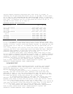
POWER STEERING FLUID CAPACITY
Application Pump Capacity System Capacity
All Models ............ 1.0 Pt. (0.5L) ......... 1.5 Pts. (0.75L)
FLUID LEVEL CHECK
Fluid level is indicated by marks on reservoir or dipstick.
Ensure fluid level is at FULL COLD mark when fluid temperature is
about 70
F (21 C). Ensure fluid level is at FULL HOT mark when fluid
is at operating temperature of about 170
F (77 C).
HYDRAULIC SYSTEM BLEEDING
NOTE: If air is introduced into hydraulic system during servicing,
bleed system. Aerated fluid, which appears Light Tan in
color, results in poor steering performance and may cause
pump damage.
1) Turn ignition off. Raise and support vehicle with wheels
off ground. Turn wheels fully to left. Add power steering fluid to
FULL COLD mark on dipstick. Leave cap off. Turn wheels from side to
side several times, but DO NOT touch steering stops. Add fluid, if
necessary, to maintain level at FULL COLD mark.
2) Start engine. With engine idling, recheck fluid level. Add
fluid, if necessary, to bring level to FULL COLD mark. Install cap.
Return wheels to center position. Lower vehicle. Continue to run
engine for 2-3 minutes. Road test vehicle. Check for leaks. Ensure
fluid level is at FULL HOT mark when fluid stabilizes at operating
temperature.
ADJUSTMENTS
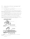
POWER STEERING PUMP BELT (SERPENTINE BELT)
1) On most applications, serpentine belt tension is
maintained by automatic tensioner and no adjustment is necessary.
Ensure tensioner indicator mark, on movable portion of tensioner, is
within limits of slotted area on stationary portion of tensioner. Any
reading outside these limits indicates a worn belt or defective
tensioner.
2) If installing NEW belt, ensure tensioner indicator is
within limit marks. If installing original belt, ensure belt operating
length and/or tensioner operating range marks are not out of limits.
Replace belt or tensioner as necessary. See appropriate SERVICE &
ADJUSTMENT SPECIFICATIONS article in ENGINE PERFORMANCE.
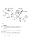
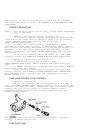
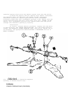
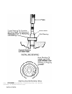
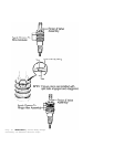
RACK BEARING PRELOAD
1) Raise and support vehicle. Turn front wheels to straight-
ahead position. Loosen adjuster plug lock nut. See Fig. 1. Turn
adjuster plug clockwise until it bottoms in housing. Back off adjuster
plug 50-70 degrees (about one flat).
2) While holding adjuster plug stationary, tighten adjuster
plug lock nut to specification. See TORQUE SPECIFICATIONS. Test drive