


Clean valve body ring grooves. Check pinion and valve
assembly drive pin. If pin is broken, replace rack and pinion
assembly.
Reassembly
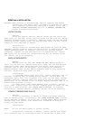
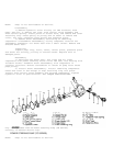
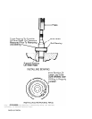
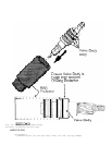
1) Apply grease to ring grooves. See Fig. 9. Install new
valve body rings on pinion and valve assembly, ensuring split tabs are
engaged and staggered. Use care not to cut rings during installation.
Apply grease to valve body rings.
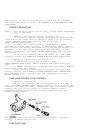
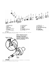
2) Install pinion and valve assembly into Ring Protector (J-
37090). See Fig. 10. Position valve assembly in ring protector so
valve body is even with bottom of protector. Allow rings to rest
inside ring protector for about 3 minutes so valve rings will size
properly.
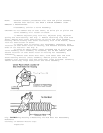
3) Using measurement taken during disassembly as a guide,
center rack in housing. Clean and apply grease to housing bore. Ensure
stub shaft bearing annulus (race) is not damaged and bearing is even
with annulus.
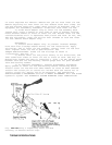
4) Align notch on valve stub shaft with second mark made
during disassembly. Using ring protector and Pinion Seal Installer (J-
29822), push pinion and valve assembly into housing bore. DO NOT
hammer or use excessive force. If assembly does not fully seat in
housing, ensure valve body rings are not binding in bore.
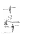
5) After assembly is seated in bore, ensure notch in stub
shaft and first mark on housing are aligned. While holding stub shaft
to prevent damage to pinion teeth, install adjuster plug lock nut and
tighten to specification. See TORQUE SPECIFICATIONS.
6) Install dust cover. Install stub shaft bearing annulus
assembly onto pinion and valve stub shaft. Install Seal Protector (J-
29810) onto valve stub shaft. Apply a small amount of grease between
stub shaft seal and stub shaft dust seal. Install seals over protector
and into housing. Install retaining ring into groove in housing.
7) Lubricate stub shaft and dust seal area with grease. Coat
rack bearing, adjuster spring and adjuster plug with grease and
install into housing. With rack centered in housing, turn adjuster
plug clockwise until it bottoms in housing, then back off 50-70
degrees (about one flat). Using an INCH-lb. torque wrench, check
pinion torque. Maximum pinion preload torque is 16 INCH lbs. (1.8 N.
m).
8) Install adjuster plug lock nut onto adjuster plug. While
holding adjuster plug, tighten lock nut to specification. Install rack
and pinion assembly. Fill and bleed system. See
HYDRAULIC SYSTEM BLEEDING under LUBRICATION.