


vi
LIST OF FIGURES
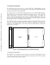
Figure 1. Front Panel and Top View (Top Shield Not Shown) .......................................................7
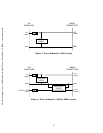
Figure 2. Power Schematic (-0001 version)....................................................................................8
Figure 3. Power Schematic (-0002 version)....................................................................................9
Figure 4. Power Schematic (-0003 & -0004 versions)....................................................................9
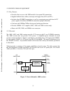
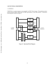
Figure 5. Functional Block Diagram.............................................................................................13
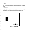
Figure 6. TTL Trigger Direction....................................................................................................14
Figure 7. ECL Trigger Direction...................................................................................................15
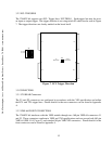
Figure 8. Pass-Through Connector Location................................................................................16
Figure 9. SUMBUS Custom Area..................................................................................................18
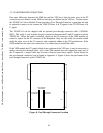
Figure 10. SUMBUS Jumper Settings............................................................................................19
LIST OF TABLES
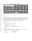
Table I. Power Supply Capabilities...............................................................................................10
Table II. VXI/VME Pass-Through Connections...........................................................................17
C&H Technologies, Inc. <> 445 Round Rock West Drive <> Round Rock, TX 78681 <> www.chtech.com