


19
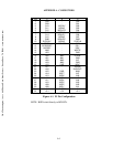
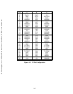
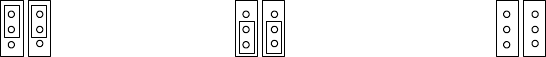
3.4.2 SUMBUS JUMPER SETTINGS
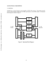
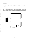
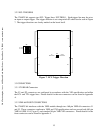
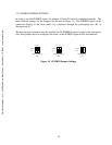
In order to use the SUMBUS signal, the jumpers J11 and J12 must be configured properly. The
three different settings for the jumpers can be seen in Figure 10. The SUMBUS signal can be
connected directly to the front panel (A), connected through the prototyping area (B), or
disconnected (C).
The pass-through connector must be installed for the SUMBUS signal to route to the front panel.
Also, both jumpers must be configured the same, or the SUMBUS signal will be disconnected.
J21
SUMBUS
CUST
DIR
J13
J21
SUMBUS
CUST
DI R
J13
J21
SUMBUS
CUST
DIR
J13
(A)
(B)
(C)
Direct Connection
Custom Connection
Disconnected
Figure 10. SUMBUS Jumper Settings
C&H Technologies, Inc. <> 445 Round Rock West Drive <> Round Rock, TX 78681 <> www.chtech.com