


18
3.4 SUMBUS CONFIGURATION
The VX402C-64 provides a direct connection of the SUMBUS signal through the pass-through
connector to the front connectors. The board also has a prototyping area so that the user can
hardwire a custom buffer for the SUMBUS signal.
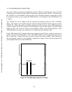
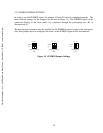
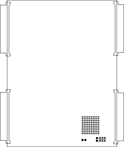
3.4.1 SUMBUS CUSTOM AREA
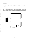
The SUMBUS custom area consists of a prototyping grid, ±12V supplies, and two jumpers for
configuring the signal. The prototyping area is a 10x10 grid of 0.1” spaced through-hole pads
which can be used in any way desired. The SUMBUS signal can be wired to the prototyping area
using the two pads next to jumpers J21 and J13, and the jumpers must be configured to the
proper setting. The location of the custom area can be seen in Figure 9.
J1
J2
P1
P2
SUMBUS
CUSTOM AREA
-
12V
+
12V
J21
J13
Figure 9. SUMBUS Custom Area
C&H Technologies, Inc. <> 445 Round Rock West Drive <> Round Rock, TX 78681 <> www.chtech.com