


16
3.3.3 PASS-THROUGH CONNECTORS
One major difference between the VME bus and the VXI bus is that the outer rows of the P2
connector are not defined on the VME bus and they are defined on the VXI bus. For this reason,
the VX402C-64 Active Module Carrier provides a Pass-Through Connector system that be used
to optionally connect or not connect the VME P2 Rows A & C signals to the VXI P2 Rows A &
C signals.
The VX402C-64 can be shipped with an optional pass-through connector cable (11028508-
0001). This cable is used to make internal connections between the P2 and J2 connectors on the
VX402C-64. When the cable is installed, signals on the J2 connector of the VME module are
routed to signals on the P2 connector of the backplane. Only use this cable for modules which
utilize the outer rows on the J2 connector and completely adhere to the VXI specification. If the
VME module has no outer row connections, it is unnecessary to install the cable.
If the VME module has P2 signals which do not conform to the VXI spec, it may be necessary to
make a custom pass-through cable. Also, if the VME module does not support the outer row of
the J2 connector, a longer cable may be used to directly access these signals. Pinout details for
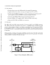
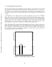
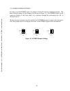
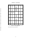
the pass-through connectors can be found in Appendix A. Figure 8 shows the placement of the
pass-through connectors on the VX402C-64.
J1
J2
P1
P2
Pass-Through
Connectors
J11
J12
To P2 Rear
Connector
To J2 Front
Connector
Figure 8. Pass-Through Connector Location
C&H Technologies, Inc. <> 445 Round Rock West Drive <> Round Rock, TX 78681 <> www.chtech.com