


15
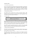
3.2.2 ECL TRIGGERS
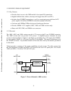
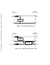
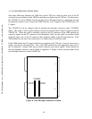
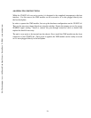
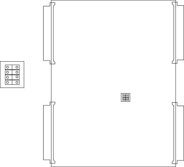
The VX402C-64 supports two ECL Trigger lines: ECLTRG0-1. Each trigger line may be set as
an input or output trigger. The trigger direction is set using switch S2 which can be seen in Figure
7. The trigger directions are clearly marked on the board itself.
J1
J2
P1
P2
S2
FROM
BACKPLANE
TO
BACKPLANE
S2
ECL
TRG
ON
ECL
TRG0
ECL
TRG1
1
Figure 7. ECL Trigger Direction
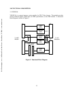
3.3 CONNECTORS
3.3.1 VXI REAR Connectors
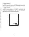
The P1 and P2 connectors are configured in accordance with the VXI specification and utilize
the ECL and TTL trigger lines. Pinout details for the rear connectors can be found in Appendix
A.
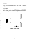
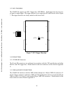
3.3.2 VME-64 FRONT CONNECTORS
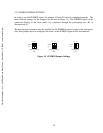
The VX402C-64 interfaces with the VME module through two 160 pin VME-64 connectors: J1
and J2. These connectors conform to VME and VXI specifications and can accept both 160 pin
VME-64 (DIN 41 612 type C) and standard 96 pin VME/VXI connectors. Pinout details for the
front connectors can be found in Appendix A.
C&H Technologies, Inc. <> 445 Round Rock West Drive <> Round Rock, TX 78681 <> www.chtech.com