


ANTENNA PLACEMENT
8
NOTE: Once you have made the connections for the 5-pin door lock harness, you will need to plug the
door lock harness into the main module 5-pin plug on the front of the unit.
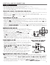
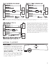
“Type B” (-) Negative (5-pin harness)
Ground
UNLOCK
LOCK
GREEN/BLACK Unlock
GREEN/WHITE Not Used
RED/BLACK
BLUE/BLACK Lock
BLUE/WHITE Not Used
MODULE
NOTE: Connect the RED WITH
BLACK STRIPE wire to ground.
FUSE
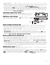
“Type A” (+) Positive (5-pin harness)
NOTE: Connect the RED WITH
BLACK STRIPE wire to +12V
constant fused at 30 amps.
UNLOCK
LOCK
GREEN/BLACK Unlock
GREEN/WHITE Not Used
RED/BLACK
BLUE/BLACK Lock
BLUE/WHITE Not Used
MODULE
+12V Constant
FUSE
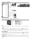
Once you have determined that your door locks are Type
C system, you must cut the unlock wire in two. Now you
need to determine which wire is coming from the switch
and the motor sides of each lock and unlock wire. First,
test the lock wires, press and hold the door lock switch
in the lock position. Test both lock wires, the wire
that shows (+) positive, and the RED light glows bright,
will be the switch side and the other wire will be the
motor side of this circuit. Mark these wires. Repeat
these steps for the unlock wire by pressing and holding
the door lock switch in the unlock position. The wire
that shows (+) positive, and the RED light glows bright,
will be the switch side and the other wire will be the
motor side of the unlock circuit.
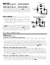
“Type C” Reverse Polarity
(5-pin harness)
NOTE: You will need to cut factory wiring
to make an end to end connection, see
“Making Connections” on pages 3-4.
POWER
DOOR
LOCK
MOTOR
LOCK
UNLOCK
GREEN/BLACK Unlock
GREEN/WHITE Unlock
RED/BLACK
BLUE/BLACK Lock
BLUE/WHITE Lock
MODULE
+12V
Constant
FUSE
NOTE: Connect the RED WITH BLACK STRIPE wire
to +12V constant power fused at 30 amps.
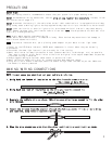
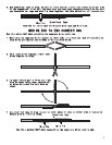
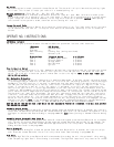
ANTENNA PLACEMENT
Run the antenna up the windshield pillar
on the driver’s side and across the top of
the windshield to the center, behind the
rearview mirror. Use the antenna clips
provided to hold it in place. Be sure to
expose the full length of the clear antenna.
It will perform best if mounted vertically,
below the dark windshield tint. Never leave
antenna in headliner.
Each receiver is tested to more than 800
feet of clear air reception. Many times
you will see a higher range. Many factors
will affect the range, including the amount
of radio signals in the area, battery
strength, window tint, etc.
Control
Module
Antenna Wire
Antenna Tube