


5
LOCATING & MAKING CONNECTIONS
MOUNTING AND CONNECTING THE SIREN
Select a location under the vehicle's hood for the siren.
•The mounting location should be solid and have no moving parts nearby.
•For the loudest sound, the siren should point down.
•The siren should not point straight up as moisture could collect in the siren horn.
•To prevent water damage, the siren should not be mounted in a wheel well, directly behind the radiator
grill, or close to the ground.
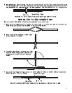
Once you select a location, follow these steps to mount the siren:
1.Using the siren base as a template, mark the three mounting holes.
2.Drill an 1/8" hole at each mounting hole location, taking care not to damage anything behind the mounting
surface.
3.Secure the siren to the mounting location with at least two of the mounting screws.
4.Connect the siren's BLACK wire to the third mounting screw, using the spade connector. Make sure this
is a solid ground.
5.Connect the siren's RED wire to the module's GREY wire.
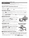
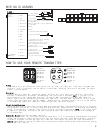
FINDING CONSTANT AND IGNITION POWER
Your system requires 12 volts constant and ignition 12 volt that is only on when the ignition is on.
1.There is usually a large gauge wire going to your ignition switch. Probe this wire. Confirm that the
light comes on or the meter indicates 12 volts. This wire will show positive voltage in all key positions.
2.Connect the RED wire from the harness to this wire.
3.Connect the BLACK wire from the harness to a clean chassis ground using the spade terminal. TEST: Press
transmitter Button #1 and the siren should chirp once. Wait 5 seconds, then press transmitter Button
#1 again, and the siren should chirp twice.
4.Probe for a wire that has 12 volts only when the ignition is on. Confirm this by turning the ignition
switch on and off while probing each wire, this wire will not show 12 volts with the key off.
5.Connect the RED WITH BLACK STRIPE wire to this wire. TEST: Turn the ignition switch to the ON position
and then press transmitter Button #1, the system should not arm. If it does, you are not connected to
the ignition wire.
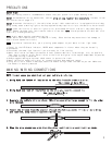
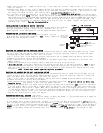
CONNECTING THE STARTER IMMOBILIZER
Locate the cranking wire in the ignition switch harness. The
cranking wire will show 12 volt only when the key is in the cranking
position. Cut the wire in two. Try to crank the engine, it should
not crank.
1.Connect the control module’s ORANGE wire (-) output when armed
to the optional starter immobilizer ORANGE wire.
2.Connect the wire coming from the ignition switch to the RED
wire on the starter immobilizer, connect the other wire to
the WHITE wire on the starter immobilizer.
3.Use a wire tie to secure the starter immobilizer relay to a
non-moving part under the dash.
4.TEST: Press transmitter Button #1 to arm the system and then
try to start the engine, it should not start. Press Button #1 again to disarm the system. This time
the engine should start. Make sure all your connections are electrically sound and taped.
87A
85
86
87
30
ORANGE
WHITE TO STARTER
IGNITION
CRANKING
WIRE
RED
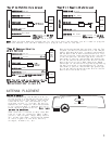
FINDING THE PARKING LIGHT WIRE
1.Locate the wire coming from the back of your vehicle’s light
control switch.
2.Use the vehicle's wiring color code chart to find the parking
light wire, or simply connect this wire to the parking light wire
usually found under the hood.
3.Turn on the parking lights. Test for a wire that indicates
12 volts only when the parking lights are on. This is a positive
parking light wire.
4.Connect this wire to the BROWN wire from the wiring harness.
5.TEST: Press transmitter Button #1, the parking lights
should flash once, wait 5 seconds, then press the transmitter
Button #1 again and the parking lights should flash twice,
and then stay on for 30 seconds.
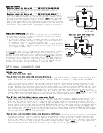
6.If the light control switch is located on your steering column,
most likely it will be a (-) negative parking light wire and
will require Part #775 to connect. See diagram above.
DETERMINING YOUR VEHICLE'S DOOR PIN SWITCH TYPE (Dome Light)
NOTE: You must connect the alarm to the door pin switch for the alarm to function properly.
1.On some vehicles this wire might also be called a door trigger and is usually behind the driver's kick
panel. Some vehicles have logic controlled dome and courtesy lights that turn on differently depending
on which vehicle door is opened. Be sure to locate a wire that is triggered from all your vehicle's
doors.
2.Attach your meter or test light's positive lead to a point on the fuse block that has constant 12 volts.
Use the other lead to probe the door pin switch wire. Then open the door. If the test light turns on
or the meter indicates 12 volts, your vehicle has a negative (-) switch door pin.
3.If your door pin switch tests as a (-) negative, connect the BLACK WITH YELLOW STRIPE wire from the
main wiring harness to this wire.
DO NOT USE THE RED WIRE,
TAPE OFF.
Optional part #775 required.
NEGATIVE PARKING LIGHT DIAGRAM ONLY
87a
To (-)Parking
Light Output
Brown wire
from 16-pin
harness
YELLOW
BLACK
WHITE
BLUE
RED
Ground