


7
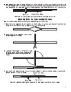
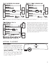
OPTIONAL CONNECTIONS
light will glow bright on both the lock and the unlock wires. Press and hold the lock button on the
switch and test the lock wire. The correct wire will test (+) positive and the RED light will glow
bright. Release the lock button and this wire should show a (-) negative and the GREEN light will glow
bright. Now press and hold the unlock button on the switch and test the unlock wire. The correct wire
will test (+) positive and the RED light will glow bright. Release the unlock button and this wire
should show a (-) negative and the GREEN light will glow bright. Your vehicle has a “Type A” door locking
system. Make sure to mark which wire is lock and unlock. Connecting Door Locks. NOTE: “Type A” and “Type
C” locks will test the same. Make sure you run both tests before making your connections.
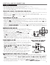
“Type B” Door Lock Test (Most Imports, some newer Fords)
Probe both of your door lock wires going to the door lock switch usually located in the driver’s kick
panel. Probe the lock and the unlock wires, the test probe will glow both GREEN and RED (dimly) on
both the lock and the unlock wires. Press and hold the lock button on the switch and test the lock
wire. The correct wire will test (-) negative and the GREEN light will glow bright. Release the lock
button and this wire should again glow both GREEN and RED (dimly). Now press and hold the unlock button
on the switch and test the unlock wire. The correct wire will test (-) negative and the GREEN light
will glow bright. Release the unlock button and this wire should again glow both GREEN and RED (dimly).
Your vehicle has a “Type B” door locking system. Make sure to mark which wire is lock and unlock.Make
sure to mark which wire is lock and unlock.
“Type C” Door Lock Test (Most Fords, some Chryslers, GM Trucks)
Once you have located the lock and unlock wires in the vehicle using the wire color chart in this manual
or from our website, you will need to perform the same test as for the Type A system. Once you have
completed this test, and it tests the same as a Type A (as it should) you will need to cut the lock
wire in two. Now try the door lock switch in both the lock and unlock positions. The door locks should
not function, this is a Type C system. Proceed to Connecting Door Locks. NOTE: If for any reason the
doors unlock but do not lock with this wire, cut in two, this is a Type A system.
TESTING: Door Locks
There are three basic types:
“Type A” Door Lock Test (Most GMs and some Chryslers)
Probe both of your door lock wires going to the door lock switch usually located in the driver’s kick
panel. Probe the lock and the unlock wires, the test probe will show a (-) negative and the GREEN
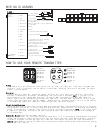
NEGATIVE OUTPUTS
Negative output #2, Button #2 - the WHITE WITH YELLOW STRIPE
wire is used to operate the car starter (optional), etc. The
negative output will pulse for one half second by pressing
transmitter Button #2.
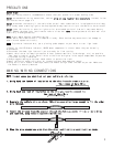
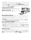
Negative output #3, Button #3 - the WHITE WITH RED STRIPE wire
is used to operate a power trunk release, window roll-up module,
etc. This negative output will pulse for one half second, or for
as long as transmitter Button #3 is pressed. NOTE: Part #775 must
be used since this negative output is only rated for 200mA (1/5
amp). Since most power trunk releases are positive controlled and
draw 5 to 6 amps, this relay (Part #775) handles the load and also
can convert the release signal from negative to positive polarity.
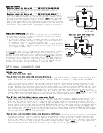
DOME LIGHT SUPERVISION (Optional)
The dome light supervision wire on the vehicle is the same wire
as your door pin wire. It can be located at the door pin switch
or under dash courtesy lights.
• If this wire tests (+) positive when the door is open (as with
most Fords) and when the door is closed, this wire tests as a
(-) negative, this is (+) positive dome light.
• If this wire tests (-) negative, when the door is open and when
the door is closed, this wire tests as a (+) positive, this is
a (-) negative dome light.
If your dome light is a (-) negative (as most others are), connect
the VIOLET wire to the domelight/doorpin wire from the 16-pin
harness. If your dome light is (+) positive (most Fords) you must
add Part #775 to use this option. See diagram. NOTE: When testing
the door pin wire, make sure the dome light is on. Some vehicles,
if the door is left open for a period of time, the dome light will
go out, resulting in a false reading. This is the same wire that
is used for the door pin switch and will test the same.
87a
TO FACTORY TRUNK WIRE
+12 VOLT FUSED
AT 20 AMPS
WHITE/RED
FROM
ALARM
Optional part #775 required.
DO NOT USE,
TAPE OFF.
87a
To Dome Light
Circuit
(-) VIOLET
FROM 16-pin
wire harness.
YELLOW
BLACK
WHITE
BLUE
RED
+12 VOLT FUSED
AT 5 AMPS