


Fold out folded page 2-33.
All lock nuts are to be replaced. All tightening torque values are to be taken from the current repair
instructions and must be observed at all times.
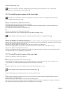
2.2 To install the level sensor at the front right
Cars with an air suspension front axle already have a level sensor.This is to be replaced with the level
sensor supplied with the parts kit.
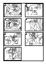
A
Only for cars without an air suspension front axle.
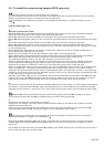
Mounting points for the level sensor at the front right:
The holder with the fitted level sensor is to be installed using the mounting screw (1) on the control arm (3).
The hole (2) is used as a locking device
The angle joint is mounted on the control arm (3).
B
Only for cars without an air suspension front axle.
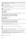
Install the level sensor (4) on the holder (6) using two Allen bolts, M5 x 10 (5).
See the position of the locking device (7) and the threaded sleeve (see magnified view).
C
Only for cars without an air suspension front axle.
Remove the nut SW16 mm from the mounting screw (1) on the control arm (3) and pull out the mounting screw (1).
Position the holder (6) with the level sensor (4) and secure the control arm (3) with the mounting screw (1) and the
lock nut SW 16 mm supplied in the parts kit.
Install the angle joint (8) on the control arm (3) and secure it with a nut SW10 mm.
Connect the angle joint (8) to the lever on the level sensor (4) and secure it with a nut SW10 mm (9).
Only for cars with an air suspension front axle.
Undo the nut SW10 mm (9) and release the angle joint (8). remove the level sensor (4) in the car (see Figure B)
and replace it with the one supplied in the parts kit.
2.3 To install the level sensor at the rear right
Only for cars without a level control system.
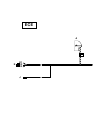
D
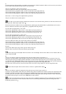
Mounting points for the level sensor at the rear right:
The holder with the fitted level sensor and the threaded plate is to be installed on the holes (10). Fit the clip
on the holder (11) on the rear axle swinging arm and secure the control rod.
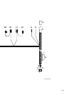
E
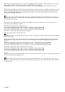
Install the level sensor (12) on the holder (14) using two Allen bolts, M5 x 10 (13).
See the position of the threaded sleeve (see magnified view).
F
Fit the threaded plate (15) into the holes (10) in the frame from the rear.
G
Fit the holder (14) wit the level sensor (12) on to the thread and the journal of the threaded plate and secure
it with a lock nut SW 10 mm (16).
Place the clip (17) on the holder (11) for the rear axle swinging arm.
Connect the lever on the level sensor (12) to the holder (11) for the rear axle swinging arm using the control rod
(18). Secure the control rod (18) with the lock nuts SW 10 mm (19 and 20).
EN/2-7