


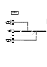
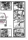

Connect cables G1 to G3 on the xenon wiring harness as follows:
Connect branch G1, grey/white cable, to slot 2 of the black 6-pin plug X1451 (G).
Connect branch G2, grey/brown cable, to slot 3 of the black 6-pin plug X1451 (G).
Connect branch G3, grey/green cable, to slot 6 of the black 6-pin plug X1451 (G).
All cars:
Connect the black 6-pin plug X1451 (G) to the level sensor.
Seal the hole in the floor of the boot with the grommet (F).
Ensure that the grommet (F) is fitted so that the car is watertight and that the cables do not interfere with any
other components.
G
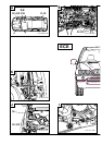
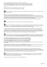
Only for cars with an optional equipment wiring harness above level 2 (see section 1):
Lay branch I, yellow/white cable, parallel to branches G1 to G3 (see Figure E) into the boot. Lay branch I on the
wiring harness along the battery positive distributor, continue behind the boot trim (10) to the 6-pin plug X1310S
(11). Cut branch I, yellow/white cable, to size and connect it to the yellow/white cable from slot 2 of the 6-pin plug
X1310S (11) using the double mini connector supplied in the parts kit (see magnified view).
Drill two holes in the boot trim (10) and secure branch I to them using cable ties (12) (see magnified view).
Ensure that the spare wheel cannot chafe on branch I (yellow/white cable).
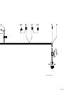
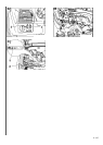
H, I
Figures H and I shows the cable positions for cars with an optional equipment wiring harness up to level 2
(see section 1). In cars with an optional equipment wiring harness above level 2, branch I, yellow/white cable, is to
be connected to the 6-pin plug X1310S at the rear left of the boot (see Figure G).
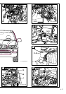
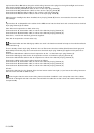
Lay branches H1 to H4, yellow/red, yellow/brown, blue/red and blue/brown cables, and branch I, yellow/white
cable(branch I only on cars with an optional equipment wiring harness up to level 2), along the vehicle wiring
harness behind the module holder in the passenger footwell to the left-hand side of the car, through the additional
passage hole in the front bulkhead grommet (13) and through the grommet (14) into the engine compartment.
Lay the cables along the vehicle wiring harness on the inside wing to near the left headlight.
The left front bulkhead grommet (13) does not have an additional passage hole for retrofit wiring harnesses in
the first cars in the series. In this case the cables H1 to H4 and I (only on cars with an optional equipment wiring
harness up to level 2) are to be laid along vehicle wiring harness through the front bulkhead grommet (13).
Connect branches H1 to H4 to the casing H (X1034, 4-pin. natural) as follows:
Connect branch H1, yellow/red cable, to slot 1 of the 4-pin plug X1034 (H).
Connect branch H2, yellow/brown cable, to slot 2 of the 4-pin plug X1034 (H).
Connect branch H3, blue/red cable, to slot 3 of the 4-pin plug X1034 (H).
Connect branch H4, blue/brown cable, to slot 4 of the 4-pin plug X1034 (H).
After the xenon headlight has been installed, the 4-pin plug X1034 (H) is to be connected to the servo motor for
the headlight.
Disconnect the 42-pin blue plug X1170 (15) from the ABS/DSC control module, release the plug strip, remove the
blind stopper from slot 18 and connect branch I, yellow/white cable, to slot 18.
Engage the plug strip, connect the 42-pin blue plug X1170 (15) to the ABS/DSC control module and secure it.
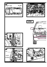
J
Lay branches J1 to J3, black/white, black/grey and black/green cables, and cables K1 to K4, yellow/black,
yellow/brown, blue/black and blue/brown cables, through the additional passage hole in the right front bulkhead
grommet near the electrics box and then through the grommet (16) into the engine compartment. Lay branches J1
to J3 and K1 to K4 along the vehicle wiring harness on the inside wing towards the front.
The right front bulkhead grommet does not have an additional passage hole for retrofit wiring harnesses in
the first cars in the series. In this case the cables J1 to J3 and K1 to K4 are to be laid along vehicle wiring
harness through the front bulkhead grommet.
Lay branches J1 to J3 to the engine near the washer water tank.
EN/2-103