


F
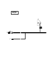
Lay branches I1 to I3 (grey/white, grey/brown and grey/green cables) forwards a little on the rear axle, secure them
to the cable holder (8) and lay them to the level sensor (9).
Only for cars without a level control system:
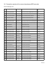
Connect cables I1 to I3 on the xenon wiring harness as follows:
Connect branch I1, grey/white cable, to slot 2 of the black 6-pin plug X1451 (I).
Connect branch I2, grey/brown cable, to slot 3 of the black 6-pin plug X1451 (I).
Connect branch I3, grey/green cable, to slot 6 of the black 6-pin plug X1451 (I).
Seal slots 1, 4 and 5 using the supplied blind grommets.
Only for cars with a level control system:
Cars with a level control system already have a branch of the vehicle wiring harness to the level sensor at the
rear right and a black 6-pin plug X1451.
Disconnect the three cables in the car (yellow/brown, yellow/grey and yellow/white or yellow/black) and connect
them as follows to the black 6-pin plug X1451 (I) supplied with the parts kit:
On cars with air suspension on one axle:
Connect the yellow/black cable to slot 1 of the black 6-pin plug X1451 (I).
Connect the yellow/brown cable to slot 4 of the black 6-pin plug X1451 (I).
Connect the yellow/grey cable to slot 5 of the black 6-pin plug X1451 (I).
On cars with air suspension on both axles:
Connect the yellow/brown cable to slot 1 of the black 6-pin plug X1451 (I).
Connect the yellow/grey cable to slot 4 of the black 6-pin plug X1451 (I).
Connect the yellow/white cable to slot 5 of the black 6-pin plug X1451 (I).
Connect cables I1 to I3 on the xenon wiring harness as follows:
Connect branch I1, grey/white cable, to slot 2 of the black 6-pin plug X1451 (I).
Connect branch I2, grey/brown cable, to slot 3 of the black 6-pin plug X1451 (I).
Connect branch I3, grey/green cable, to slot 6 of the black 6-pin plug X1451 (I).
All cars:
Connect the black 6-pin plug X1451 (I) to the level sensor (9).
Seal the hole in the floor of the boot with the grommet (H).
Ensure that the grommet (H) is fitted so that the car is watertight and that the cables do not interfere with any
other components.
G
Only for cars with an optional equipment wiring harness above level 2 (see section 1):
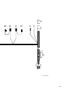
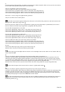
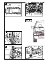
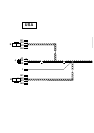
Lay branch J, yellow/white cable, parallel to branches I1 to I3 (see Figure E) into the boot. Lay branch J on the
wiring harness along the battery positive distributor, continue behind the boot trim (10) to the 6-pin plug X1310S
(11). Cut branch J, yellow/white cable, to size and connect it to the yellow/white cable from slot 2 of the 6-pin plug
X1310S (11) using the double mini connector supplied in the parts kit (see magnified view).
Drill two holes in the boot trim (10) and secure branch J to them using cable ties (12) (see magnified view).
Ensure that the spare wheel cannot chafe on branch J (yellow/white cable).
H, I
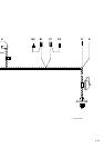
Only for cars with an optional equipment wiring harness up to level 2 (see section 1):
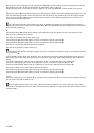
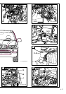
Lay branch J, yellow/white cable, along the vehicle wiring harness behind the module carrier in the passenger side
footwell to the left-hand side of the car, through the additional passage hole in the front bulkhead grommet (13)
and the grommet (14) into the engine compartment and then along the vehicle wiring harness on the inside wing
to the 42-pin blue plug X1170 (15) on the ABS/DSC control module.
The left front bulkhead grommet (13) does not have an additional passage hole for retrofit wiring harnesses in
the first cars in the series. In this case the cable J is to be laid along vehicle wiring harness through the front
bulkhead grommet (13).
EN/2-51