


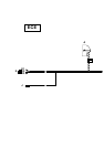

D
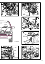
Disconnect the 54-pin black plug X10117 (5) from the light module (6) on the A pillar on the passenger side and
take the plug strip off the casing. Lay branches D and E, yellow/red and blue/red cables, to there. Connect branch
D, yellow/red cable, to slot 27 of the 54-pin plug X10117 (5).
Connect branch E, blue/red cable, to the blue/red cable from slot 25 of the 54-pin plug X10117 (5) using a double
mini connector from the parts kit (7).
Ensure that the casing and plug strip can be assembled and connected to the light module (6) after the mini
connector (7) has been connected.
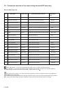
Disconnect the following cables from the plug strips of plug X10117 (5), fit the contact parts to them supplied in
the parts kit and connect them to the 10-pin casing (G).
Two yellow/brown and two blue/brown cables are to be disconnected but must not be mixed up. Keep to the
order described to avoid confusion.
First disconnect the following four cables:
Slot 2, blue/red cable;
Slot 3, blue/brown cable;
Slot 4, yellow/red cable;
Slot 5, yellow/brown cable.
Remove the contact parts from these cables, strip the cables and fit the contact parts supplied in the parts kit to
them.
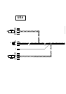
Connect the cables as follows to the black 10-pin plug X1B* (G) supplied with the kit:
Connect the blue/red cable to slot 1 of the black 10-pin plug X1B* (G).
Connect the blue/brown cable to slot 2 of the black 10-pin plug X1B* (G).
Connect the yellow/red cable to slot 3 of the black 10-pin plug X1B* (G)
Connect the yellow/brown cable to slot 4 of the black 10-pin plug X1B* (G)
Now disconnect the following four cables:
Slot 20, blue/black cable;
Slot 21, blue/brown cable;
Slot 22, yellow/black cable;
Slot 23, yellow/brown cable.
Remove the contact parts from these cables, strip the cables and fit the contact parts supplied in the parts kit to
them.
Connect the cables as follows to the black 10-pin plug X1B* (G) supplied with the kit:
Connect the blue/black cable to slot 7 of the black 10-pin plug X1B* (G).
Connect the blue/brown cable to slot 8 of the black 10-pin plug X1B* (G).
Connect the yellow/black cable to slot 9 of the black 10-pin plug X1B* (G)
Connect the yellow/brown cable to slot 10 of the black 10-pin plug X1B* (G)
Connect the 10-pin black plug X1B* (G) to branch F of the xenon wiring harness and stow the plug connector so
that it does not interfere with any other components.
Assemble the 54-pin plug X10117 (5), connect it to the light module (6) and secure it.
Branches I1 to I3 go further back along the vehicle wiring harness towards the rear.
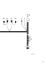
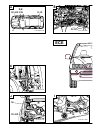
E
In cars with a vehicle wiring harness above level 2 (see section 1), branch J (yellow/white cable) on the xenon
wiring harness goes parallel to branches I1 to I3 into the boot.
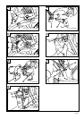
Lay branches I1 to I3 (grey/white, grey/brown and grey/green cables) along the right-hand sill wiring harness to
the rear, along the vehicle wiring harness behind the right-hand boot trim and then along the vehicle wiring
harness to the floor of the boot.
Remove the 20 mm sealing stopper from the floor of the boot (the hole in Figure E is already sealed with the
grommet (H)), deburr the hole and treat it with the normal BMW anti-corrosion coatings.
Place grommet H on cables I1 to I3, grey/white, grey/brown and grey/green cables, and thread cables I1 to I3
through the holes to the underside of the car.
The rear axle is beneath the hole.
2-50/EN