


2.7 To install the xenon wiring harness (US cars only)
The xenon wiring harness is to be secured using cable ties.
Ensure that cables and other lines are not kinked or damaged when they are being installed in the car and that
they do not impair the freedom of movement of other components.
If the specified pins or chambers are already in use, bridges, double crimps or parallel end stops are to be
used.
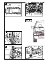
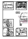
Fold out folded page 2-129
A
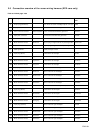
Overview of connection points
Branch A (X991, 26-pin plug, Bordeaux) is to be connected to the control module for the automatic headlight
adjustment control system on the module holder behind the glove box.
Branch B1 (triple joint connector X10466*) is to be fitted in the connector box behind the glove box.
Branch B2 (white/red/yellow cable) is to be connected to the K-BUS terminal connector (X10116) behind the glove
box.
Branch C1 (triple joint connector X1608*) is to be fitted in the connector box behind the glove box.
Branch C2 (brown/black cable) is to be connected to the terminal 31 connector (X596) behind the glove box.
Branch D (yellow/red cable) is to be connected to slot 27 in the light module (X10117, 54-pin, black) on the A pillar
on the passenger side.
Branch E (blue/red cable) is to be connected to the blue/red cable from pin 25 on the light module (X10117,
54-pin, black) using a double mini connector.
The rubber grommet (F) is used to seal the cable passage on the floor of the boot.
Cable G1, grey/white cable, is to be connected to slot 2 of branch G (X1451, 6-pin, black), cable G2, grey/brown
cable, to slot 3 and cable G3, grey/green cable, to slot 6. Any cables in the car for the level sensor are to be
repinned (see section 2.7-F). Branch G is then to be connected to the level sensor at the rear right.
Cable H1, yellow/red cable, is to be connected to slot 1 of branch H (X1034, 4-pin, natural), cable H2,
yellow/brown cable, to slot 2, cable H3, blue/red cable, to slot 3 and cable H4, blue/brown cable, to slot 4. Branch
H is to be connected to the servo motor on the left Xenon headlight.
Branch I (yellow/white cable) is to be connected to slot 18 of the ABS/DSC control module in the front left of the
engine compartment in cars with an optional equipment wiring harness up to level 2. In cars with an optional
equipment wiring harness above level 2, there is a yellow/white cable in the boot at the rear left on the 6-pin plug
X1310S on slot 2, which comes from the ABS/DSC control module, slot 18. Connect branch I (yellow/white cable)
to this cable using a double mini connector.
Cable J1, black/white cable, is to be connected to slot 2 of branch J (X10275, 6-pin, black), cable J2, black/grey
cable, to slot 3 and cable J3, black/green cable, to slot 6. Any cables in the car for the air suspension are to be
repinned (see section 2.7-F). Branch J is then to be connected to the level sensor at the front right.
Cable K1, yellow/black cable, is to be connected to slot 1 of branch K (X1035, 4-pin, natural), cable K2,
yellow/brown cable, to slot 2, cable K3, blue/black cable, to slot 3 and cable K4, blue/brown cable, to slot 4.
Branch K is to be connected to the servo motor on the right Xenon headlight.
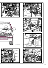
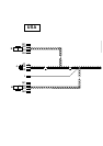
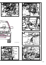
B
Connect the control module for the automatic headlight adjustment control system (1) to the module holder behind
the glove box. Connect branch A (X991, 26-pin plug, Bordeaux) to the control module for the automatic headlight
adjustment control system (1) and secure it.The xenon wiring harness goes to the right and splits near the A pillar.
Branches B1 to G3 go downwards along the vehicle wiring harness, branches B1 to C2 then go to the
connector box (2).
Branches H to K4 go upwards along the vehicle wiring harness.
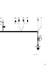
C
Release the connector box (2) and swing it forwards.
Unclip the K bus multiple connector (X10116, white/red/yellow cables) (3) and terminal 31 multiple connector
(X596, brown/black cables) (4).
If there are any unoccupied slots in the multiple connectors X10116 (3) and X596 (4), connect branches B2,
white/red/yellow cable, and C2, brown/black cable, to the corresponding cable colours.
The procedure if all the slots are occupied is described for multiple connector X10116 (3). If necessary
proceed accordingly for multiple connector X596 (4).
Disconnect a white/red/yellow cable from multiple connector X10116 (3) and connect it to the triple connector
X10466* (B1). Connect branch B2, white/red/yellow cable, to the now unoccupied slot on multiple connector
X10116 (3).
EN/2-101