


AS-1785 Installation Guide P. 7
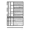
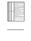
5
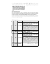
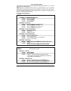
WHITE /
GREEN
(–) Disarm output
500 mA ground pulse when the Doors are unlocked
by remote control. Connect to the OEM Disarm wire
of the vehicle.
Note: The system will also give a Disarm pulse on
this wire before every remote start.
This input should be used in vehicles with positive-
switching Door pins or Dome Light circuits.
Connect to the Dome Light wire that tests +12 V
when a Door is open.
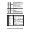
6 BLUE / WHITE
(+) Positive Door
input
Caution! The installer should use either the positive
or the negative Door input. Never use both of them
simultaneously.
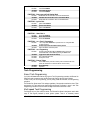
It is essential that the Remote Car Starter be
connected in such a way as will allow each one of
the Doors to turn off Ready Mode: the driver-side
Door Pin does not constitute by itself a
sufficient connection.
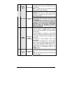
7
WHITE /
ORANGE
(–) Starter Kill
output
(armed output)
This wire will provide a constant 500 mA output
when the system is armed (locked by remote
control). It can be connected to an external Starter
Interrupt Relay.
This wire should be connected to a Single Pole
Double-Throw Relay: this wire will connect to Pin 85
on the Relay, and Pin 86 will be connected to the
Ignition wire.
The Starter Kill output becomes active during
remote starts.
One benefit of the Starter Kill is the Anti-Grind
feature. Once the vehicle has been remote started,
the Anti-Grind prevents the Starter Motor from re-
engaging when the Ignition Key is inserted in the
Ignition Switch and accidentally turned to the
CRANK position.
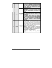
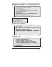
8 ORANGE
(–) Parking Brake
input
Connect to the negative Parking Brake Indicator Light wire
of the vehicle. This wire is found at the parking brake leve
r
itself.
Note: The wire should test ground when the Parking
Brake is engaged.