


3
BLACK (LONG):
Using the attached wire lug, connect the Black (long)
wire of the siren to the negative terminal of the battery or
a good ground source.
BLACK (SHORT):
Stretch the short Black antenna wire as long as pos-
sible, avoiding metal contact if possible. This is the an-
tenna wire for the alarm system; route it as high as
possible!
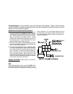
BROWN/BLACK:
This wire is used when an additional horn is connected
to the alarm system. To connect an additional horn, a
relay is required (included in the kit). The relay may be
used as a horn, park light or starter kill. The relay, when-
ever possible, should be protected from water, engine
heat or grease. NOTE:
Additional relays are avail-
able as part #AS-9256.
Refer to Figure 4 and the ac-
companying instructions for connecting the horn relay
feature.
WHITE:
This wire is used to connect the alarm system to the
motorcycle's turn signal/running lights. This feature re-
quires a relay (included in the kit). The relay may be
used as a horn, park light or starter kill. The relay, when-
ever possible, should be protected from water, engine
heat or grease. The relay should be mounted as near to
the lights as possible. NOTE:
Additional relays are
available as part #AS-9256.
Refer to Figure 6 for relay
connections.
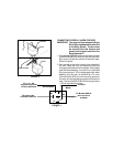
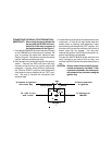
ORANGE:
This wire is used to connect the alarm system to the
motorcycle's ignition system Refer to Figure 2. This
wire must be connected for the emergency override to
function properly in case the transmitter is lost or sto-
len. When connected to the ignition switch, the wire is
connected as is. The wire contains a series resistor.
The resistor will get hot of an attempt is made to steal
the motorcycle, so make sure it is not located near low-
temperature material.
This wire can also be connected to disable the starter
or ignition. To disable a circuit on the motorcycle, a re-
lay is required (included in the kit). The relay may be
used as a horn, park light or starter kill. The relay, when-
ever possible, should be protected from water, engine
heat or grease. NOTE:
Additional relays are avail-
able as part #AS-9256.
Additionally, the wire must be
cut to remove the series resistor. The wire will then be
connected to the optional relay. Refer to Figure 5.
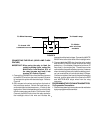
MOUNTING A RELAY
To mount a relay:
1. Screw the relay to the mounting surface, using a sheet
metal screw through the hole in the relay mounting tab.
2. Secure the relay to an existing wire harness or other
component using cable ties. Refer to Figure 3.
TO MOTORCYCLE
IGNITION CIRCUIT
FIGURE 2
ORANGE FROM ALARM
RESISTOR