


128-8121
5 of 24
5
This system is to be used in vehicles with AUTOMATIC TRANSMISSIONS only! Although this combina-
tion Keyless Entry/Remote Start unit is a sophisticated system with many advanced features, IT MUST
NOT be installed into a vehicle with a manually operated transmission. Doing so may result in serious
personal injury and property damage.
MUST HAVE a Tach Signal Input, and an Automatic Transmission.
INSTALLATION OF THE MAJOR COMPONENTS:
CONTROL MODULE:
Select a mounting location inside the passenger compartment (up behind the dashboard). The mounting
location selected must be within 24" of the ignition switch wiring harness to allow connection of the 6 pin
main wiring harness.
Be certain that the chosen location will not interfere with proper operation of the vehicle. Avoid mounting the
module to or routing the wiring around the steering shaft/column, as the module or wiring may wrap around
or block the steering wheel preventing proper control of the vehicle. Secure the module in the chosen
location using cable ties or screws as necessary.
Note: Do Not Mount The Module In The Engine Compartment, as it is not waterproof.
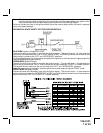
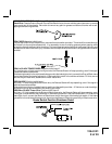
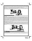
HOOD PIN SWITCH:
The hood pin switch included in this package is required for the safety shut down of the remote start unit. If
the vehicle is being worked on, this hood switch prevents the remote start activation even if the RF com-
mand to start is issued. This hood pin switch MUST be installed in all applications. Failure to install the
hood pin switch may result in personal injury or property damage. Mount the hood pin switch in an area
under the hood that is away from water drain paths. If necessary, the included brackets may be used to
move the hood pin switch away from rain gutters or allow mounting to the firewall behind the hood seal. In
either case the hood pin switch must be set up to allow the hood to depress the switch at least 1/4" when
the hood is closed and fully extended when the hood is opened. For direct mounting, a 1/4" hole must be
drilled. Carefully check behind the chosen location to insure the drill will not penetrate any existing factory
wiring or fluid lines. Drill a 1/4" hole in the desired location and thread the hood pin switch into it using a 7/
16" nut driver or deep well socket. If using the mounting bracket, first secure the bracket to the desired
location and secure the hood pin switch in the pre-threaded mounting bracket hole.
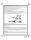
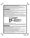
PUSHBUTTON LED SWITCH
Select a mounting location known and accessible to the operator of the vehicle. A dash knockout plug or
front dash panel is desirable as the now Pushbutton LED assembly needs the LED to be visible from the
outside of the vehicle and will be used for valet modes, programming features, programming transmitters,
and for overriding the remote start unit when the vehicle is being serviced. Inspect behind the chosen
location to insure that adequate clearance is allowed for the body of the switch, and also that the drill will not
penetrate any existing factory wiring or fluid lines. Drill a 5/16" or 8mm hole in the desired location and
mount the switch by passing the connectors, one at a time, through the panel from the front side and
pressing on the bezel until the switch is fully seated.
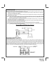
THE RECEIVER/ANTENNA ASSEMBLY:
The Receiver Antenna Assembly provided with this unit allows routing from below the dashboard for maxi-
mum operating range. Choose a location above the belt line (dashboard) of the vehicle for best reception.
Special considerations must be made for windshield glass as some newer vehicles utilize a metallic shielded
window glass that will inhibit or restrict RF reception. In these vehicles, route the antenna toward a rear
window location for best reception. Secure the antenna with double stick tape provided. After securing the
antenna with tape, we advise also securing a section of the antenna cable to a fixed support. This will
prevent the antenna from dropping down in case the double stick tape is exposed to extreme heat, which
may loosen its gummed surface. Route the connector toward the control module using caution not to pinch
the cable as this will cause poor or no RF reception to the control module.