


128-8121
10 of 24
10
YELLOW w/ BLACK Tracer Wire: + 12 Volt Alarm By - Pass Output
Note: You must disconnect the ignition input of the alarm from any other wire that it is presently connected
to in the vehicle.
This wire provides a + 12 Volt output when the ignition key is turned to the “ON” position, and 0 Volts when the ignition
key is “OFF” and when the vehicle is running under the control of the remote starter.
This wire should be connected to the ignition input of the alarm system.
The Yellow w/ Black wire output will allow you to remote start the vehicle while leaving the alarm armed, and to lock/
unlock the doors while running under control of the remote start unit.
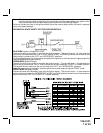
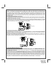
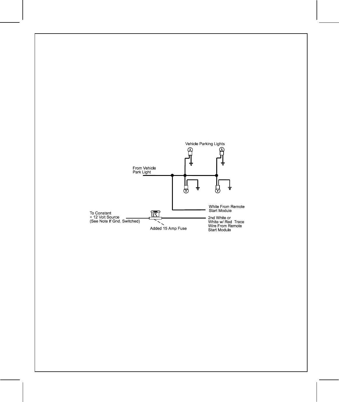
(2) WHITE Wires: Parking Light Flasher
These wires are the COMMON and NORMALLY OPEN contacts of the on-board parking lamp relay.
If the vehicle's parking lights are a +12 volt switched system, connect (1) of the White wires to a fused (15A max.)
+12 volt battery source, and connect the second White wire to the vehicle's parking light wire.
If the vehicle's parking lights are a chassis ground switched system, connect (1) of the White wires to a chassis
ground source, and connect the second White wire to the vehicle's parking light wire.
LIGHT BLUE Wire: Ignition 3 / Shock Disable Output
This wire provides a 300mA ground output that becomes active 3 seconds before the Remote Start Unit initializes,
and remains grounded while running plus an additional 4 seconds after the Remote Start Unit turns off. In all of
the applications described below, a relay will be required. The Light Blue wire can be used to accommodate the
following situations:
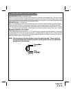
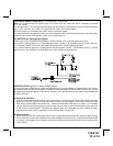
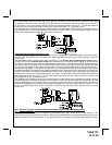
A. Shock Sensor By Pass:
If there is Shock Sensor used with an alarm system and it is not shunted during the Remote Start activation
period, then vibration from the running vehicle can cause the alarm to trigger. In this case, connect the Light
Blue Wire to terminal #86 of a external relay. Connect terminal #85 of the relay to a fused + 12 volt battery
source. Cut the shock sensor trigger wire and connect one end of the cut wire to terminal #30 and the other end
of the cut wire to terminal #87a. Just before the Remote Start unit is activated, the relay contacts will open,
preventing the shock sensor's operation until the Remote Start unit shuts off.
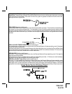
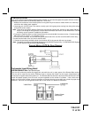
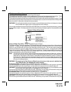
B. Ignition 3 Output:
Some newer vehicles use a third ignition wire, which is required to start and keep the vehicle's engine running.
If this is the case, connect the Light Blue wire to terminal #86 of an external relay. Connect terminal #30 & #85
to a fused + 12 volt battery source rated for a minimum of 25 Amp. Connect terminal #87 to the third ignition wire
in the vehicle.
Switch