


128-8121
16 of 24
16
wire the remaining relay contacts to perform the selected function of channel 6.
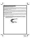
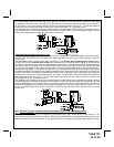
Blue/Red Wire : DELAYED 300 mA PULSED OUTPUT / CHANNEL 7
The light blue/red wire pulses to ground via an independent RF channel from the keychain transmitter. This is
a transistorized, low current output, and should only be used to drive an external relay coil.
WARNING: Connecting the light blue/red to the high current circuits, will damage the control module.
Connect the light blue/red to terminal 86 of the AS - 9256 relay (or equivalent 30 A automotive relay) and wire
the remaining relay contacts to perform the selected function of channel 7.
3 Pin Input/Output Harness:
Dark Blue/Black Trace Wire: External Trigger Input
The Dark Blue/Black trace wire allows the remote start unit to be activated from an external source. The
intent of this wire is to allow the unit to be controlled from a "POSSE/CAR-LINK" paging system or similar
device. When this wire receives a ground pulse, the unit will start the vehicle. Connect this wire to a ground
pulsed output from the controlling circuit.
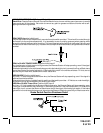
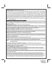
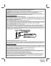
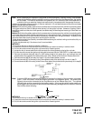
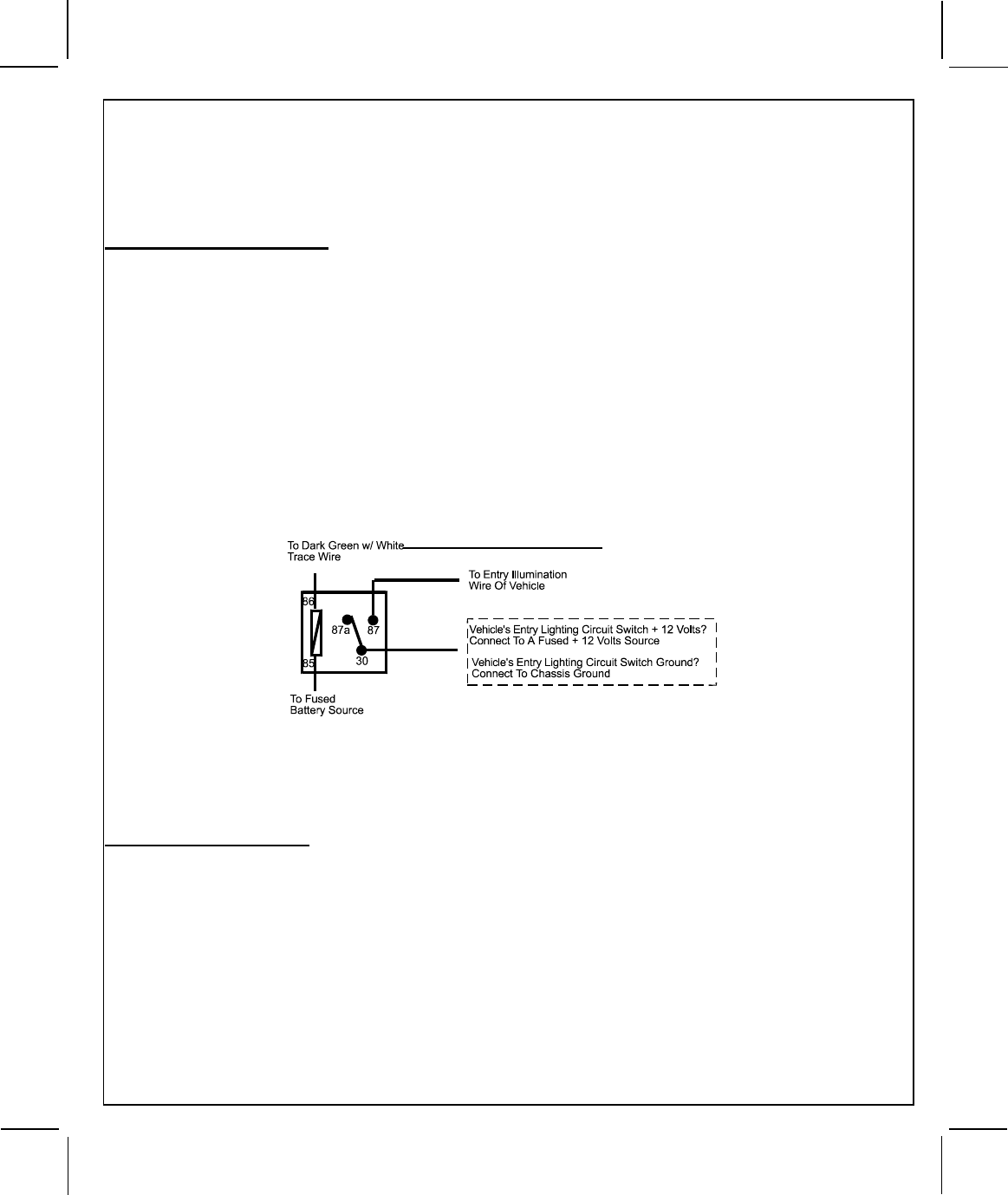
Green w/ White Trace Wire: Entry Illumination Ground Output
This wire provides a 30 second ground output (300 mA Max.) whenever the remote is used to unlock the
doors . This wire should be connected to an external relay, and wired to the vehicles interior entry lighting
whenever the optional Interior Illumination circuit is desired. See below for relay wiring details.
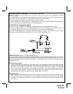
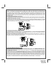
Black w/ White Trace Wire: 300 mA Horn Output
The black w/ white trace wire is provided to beep the vehicle’s horn. This is a transistorized low current
output, and should only be connected to the low current ground output from the vehicle’s horn switch.
If the vehicle uses a + 12 VDC horn switch, then connect the black w/ white trace wire to terminal 86 of the
AS 9256 relay ( or an equivalent 30 Amp automotive relay ), and connect relay terminal 85 to a fused + 12
VDC battery source. Connect relay terminal 87 to the vehicle’s horn switch output, and connect relay termi-
nal 30 to a fused + 12 VDC battery source.
Entry Illumination Detail
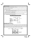
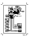
3 Pin Antenna/Receiver Connector: (White Connector)
Plug the previously routed antenna connector from the antenna receiver assemble into the mating connector
of the control module. This connector supplies 12 volts, ground and RF data from the antenna receiver to the
remote start module. Be certain this connector is firmly seated making good contact to the control unit.
TIMED START PROGRAM:
The Remote Start unit has the ability to start the vehicle automatically at timed intervals. This feature is useful
in extremely cold climates where starting the engine is the only means to keep the battery charged and fluids
warm. The operator has the option to have the unit start every 2 or 4 hours for a maximum of 48 hours. Factory
preset is to start at 4 hour intervals. To select 2 or 4 hour automatic start timer:
1. Start By Holding the Pushbutton Switch On.
2. While Holding the Pushbutton Switch Turn The Ignition Switch On Then Off
3a) Within 10 seconds of turning the ignition switch off, Release and then Push On and release the Push-
button Switch 2 times holding it on the second time until the siren and or lights flash and chirp 2 times
indicating that the 2 Hour Start Interval has successfully been set. or
3b) Within 10 seconds of turning the ignition switch off, (Step 2) Release
and then Push On and release the Pushbutton Switch 4 times holding it on the fourth time until the siren
and or lights flash and chirp 4 times indicating that the 4 Hour Start Interval has successfully been set.
Note: Once selected, 2 or 4, this timer interval will remain in memory until it is manually changed. To
change, the above sequence will have to be followed.