


128-8121
13 of 24
13
3 Pin Door Lock/Unlock Harness: (White Connector)
The Red and Green wires will provide either a pulsed ground output to the factory door lock control relay, or a
pulsed + 12 volt output to the factory door lock control relay. In either case, the maximum current draw through
these outputs must not exceed 300mA. The Red w/Black trace wire will provide a pulsed ground only, and will
only provide an output when the unlock button of the transmitter is pressed a second time after a first unlock
command was issued. This is used for second step unlock or all doors unlock in a two step circuit. In this
arrangement, Red is used to control the drivers door unlock relay, and the Red/Black will be used to control unlock
of all other doors.
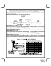
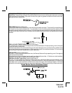
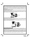
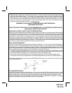
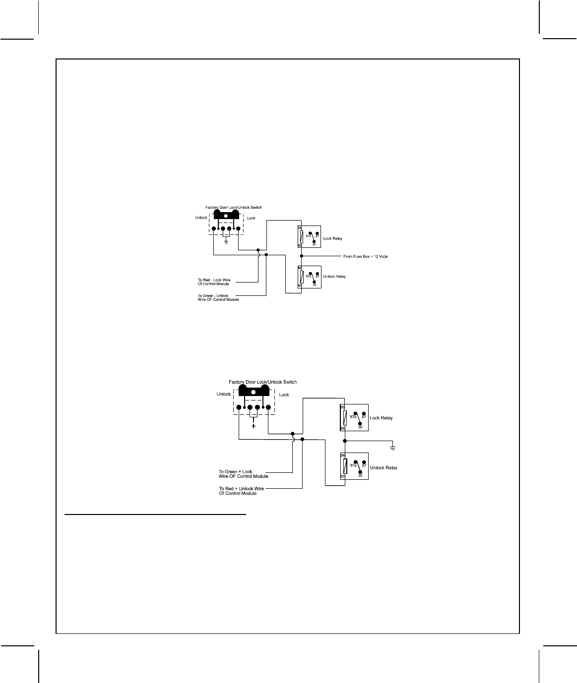
3 Wire Ground Switched Door Lock Circuits:
In this application, the Red wire of the door lock harness provides a ground pulse during the arming sequence,
or pulsed ground lock output. Connect the Red wire to the low current ground signal wire from the factory door
lock switch to the factory door lock relay.
The Green wire of the door lock harness provides a ground pulse during the disarming sequence, or pulsed
ground unlock output. Connect the Green wire to the low current ground signal wire from the factory door unlock
switch to the factory door unlock relay. See Below For Wiring Detail.
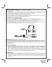
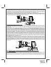
3 Wire Positive Switched Door Locks:
In this application, the Red wire of the door lock harness provides a + 12 volt pulse during the disarming
sequence, or pulsed 12 volt unlock output. Connect the Red wire to the low current 12 volt signal wire from the
factory door unlock switch to the factory door unlock relay.
The Green wire of the door lock harness provides a + 12 volt pulse during the arming sequence, or pulsed 12 volt
lock output. Connect the Green wire to the low current 12 volt signal wire from the factory door lock switch to the
factory door lock relay. See Below For Wiring Detail.
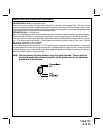
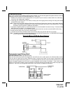
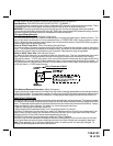
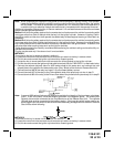
3 Wire Ground Switched 2 Step Door Locks
In this application, the red wire provides a ground pulse during arming, or the pulsed ground lock output.
Connect the red wire to the wire that provides a low current ground signal from the factory door lock switch to the
factory door lock control relay.
The green wire provides the first ground pulse during disarming, or the drivers door pulsed ground unlock
output. Connect this wire to the drivers door unlock relay that requires a low current ground signal to unlock only
the drivers door. If the vehicle does not have a separate drivers door relay, one will have to be added. Locate the
drivers door unlock motor wire and cut it at a convenient location to allow wiring of an optional relay. Connect the
door side of the cut wire to terminal 30 of the optional relay added. Connect the vehicle side of the cut wire to
terminal 87a of the optional relay added. Connect the green wire of the 3 pin harness to terminal 86 of the optional
relay added. Connect terminal 85 of the optional relay added to a fused constant + 12 volt source.