


128-8121
14 of 24
14
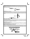
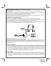
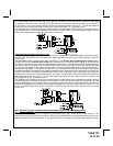
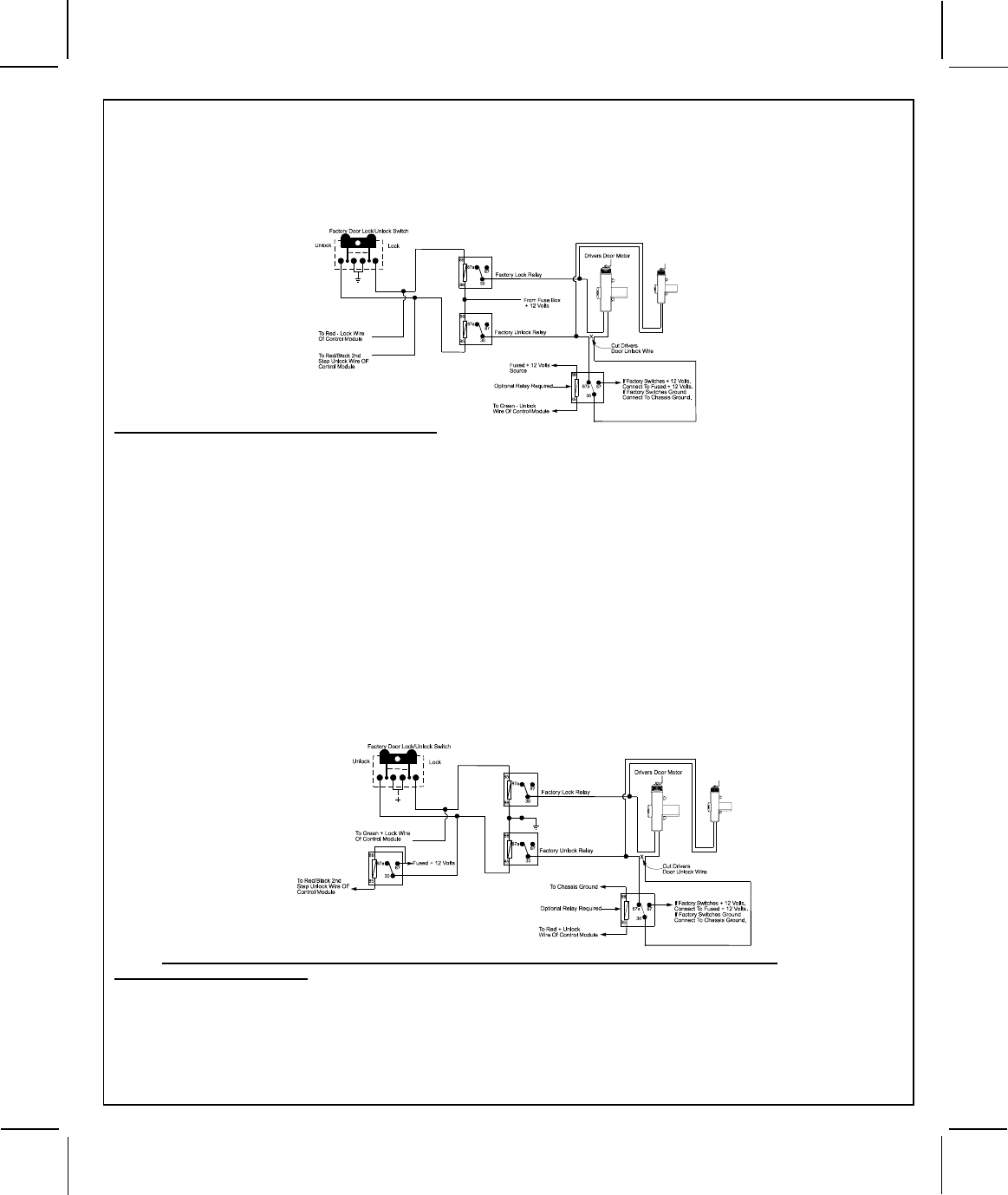
Most vehicles door lock/unlock motor legs rest at ground, and switch +12 volts to the door lock/unlock motor legs
for operation, if this is the case in the vehicle you are working on, connect the remaining terminal, 87, to a fused +
12 volt source. In the rare instance that the vehicle door lock/unlock motor legs rest at + 12 volts and switches
ground to the door lock/unlock motors, connect the remaining terminal, 87, to chassis ground.
The Red/Black wire provides a pulse ground output when the unlock button of the transmitter is pressed a second
time after disarming. Connect the Red/Black wire to the wire that provides a low current ground signal from the
factory door unlock switch to the factory door unlock control relay.
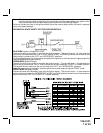
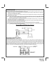
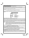
3 Wire Positive Switched 2 Step Door Locks
The green wire provides a positive pulse during arming, or the pulsed + 12 volt lock output. Connect the green
wire to the wire that provides a low current positive signal from the factory door lock switch to the factory door lock
control relay.
The red wire provides a positive pulse during disarming, or the drivers door pulsed positive unlock output.
Connect this wire to the drivers door unlock relay that requires a low current positive signal to unlock only the
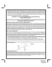
drivers door. If the vehicle does not have a separate drivers door relay, one will have to be added. Locate the drivers
door unlock motor wire and cut it at a convenient location to allow wiring of an optional relay. Connect the door side
of the cut wire to terminal 30 of the optional relay added. Connect the vehicle side of the cut wire to terminal 87a of
the optional relay added. Connect the red wire of the 3 pin harness to terminal 86 of the optional relay added.
Connect terminal 85 of the optional relay added to chassis ground. Most vehicles door lock/unlock motor legs rest
at ground, and switch +12 volts to the door lock/unlock motor legs for operation, if this is the case in the vehicle you
are working on, connect the remaining terminal, 87, to a fused + 12 volt source. In the rare instance that the vehicle
door lock/unlock motor legs rest at + 12 volts and switches ground to the door lock/unlock motors, connect he
remaining terminal, 87, to chassis ground.
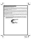
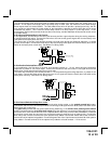
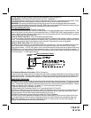
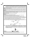
The Red/Black wire provides a pulse ground output when the unlock button of the transmitter is pressed a second
time after disarming. Because the vehicle you are working on requires a positive pulse from the factory door lock
switch to the factory door lock control relay, you will have to add a relay to invert the output polarity of this wire.
Connect the Red/Black wire to terminal 86 of the optional added relay. Connect terminal 85 & 87 to a fuse + 12 volt
source. Connect terminal 30 to the low current door unlock wire from the factory door switch to the door unlock
control relay.
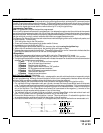
Note: Resistive Circuits, As Well As 4 Wire Polarity Reversal and 5 Wire Alternating 12 Volt
Door Lock Control Circuits
These applications require the use of additional components which may include relays, fixed resistors, or for
convenience, the AS 9159 Door Lock Interface. Refer to the AUDIOVOX Door Lock Wiring Supplement and or the
Audiovox fax back service for information on your particular vehicle for properly connecting to these types of circuits.