


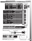
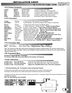
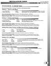
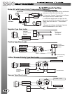
Yellow Starter 30amp output 12volts during crank only.
Green Heater 30amp output 12volts in accessory. Off during start.
Red 12 power 30amp input Constant 12volt power at ignition harness.
Red 12 power 30amp input Constant 12volt power at ignition harness.
Blue Ignition 1 30amp output 12volts in ignition and start positions.
White Select Out 30amp output Selectable Output. See jumper diagram.
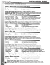
Yellow Re-Arm 0.75sec Pulse With Lock And On Shutdown.
Red/White 3rd CH Trunk Release - Active When Button #2 Is Held For 3seconds.
Brown Disarm 0.75sec Pulse With Unlock And Before Start.
Orange (-) Output (-) While Running / (-) While Locked - **Starter Program Mode.
White/Blue Siren / Horn (+) Siren / Horn Output - **User & Alarm Program Modes.
Black/White Park Brake Negative Park Brake Input - Manual Transmission Models Only.
Purple (+) Door Input Positive Door Trigger Input - Manual Trans & Alarm Units Only.
White Park Lights Positive Park light Output - 10 Amp Max.
Green/White Hood Pin Negative Hood Pin Input - MUST BE CONNECTED!!
Green (-) Door Negative Door Trigger Input - Manual Trans& Alarm Units Only
Black Ground System Ground Input - MUST BE CONNECTED!!
Pink Brake Positive Brake Input - MUST BE CONNECTED!!
Blue/White Tach Tach Signal Input - MUST BE CONNECTED ON TACH MODELS!!!
Blue Glow Plug Programmable Input - DIESEL ONLY. **Starter Program Mode.
14 Pin Connector
Green Door Lock Door Lock Output - Programmable - Menu 1 Setting 3.
Blue Door Unlock Door Unlock Output - Programmable - Menu 1 Setting 3.
3 Pin Connector Red
4 Pin Connector Blue
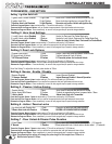
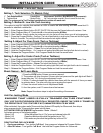
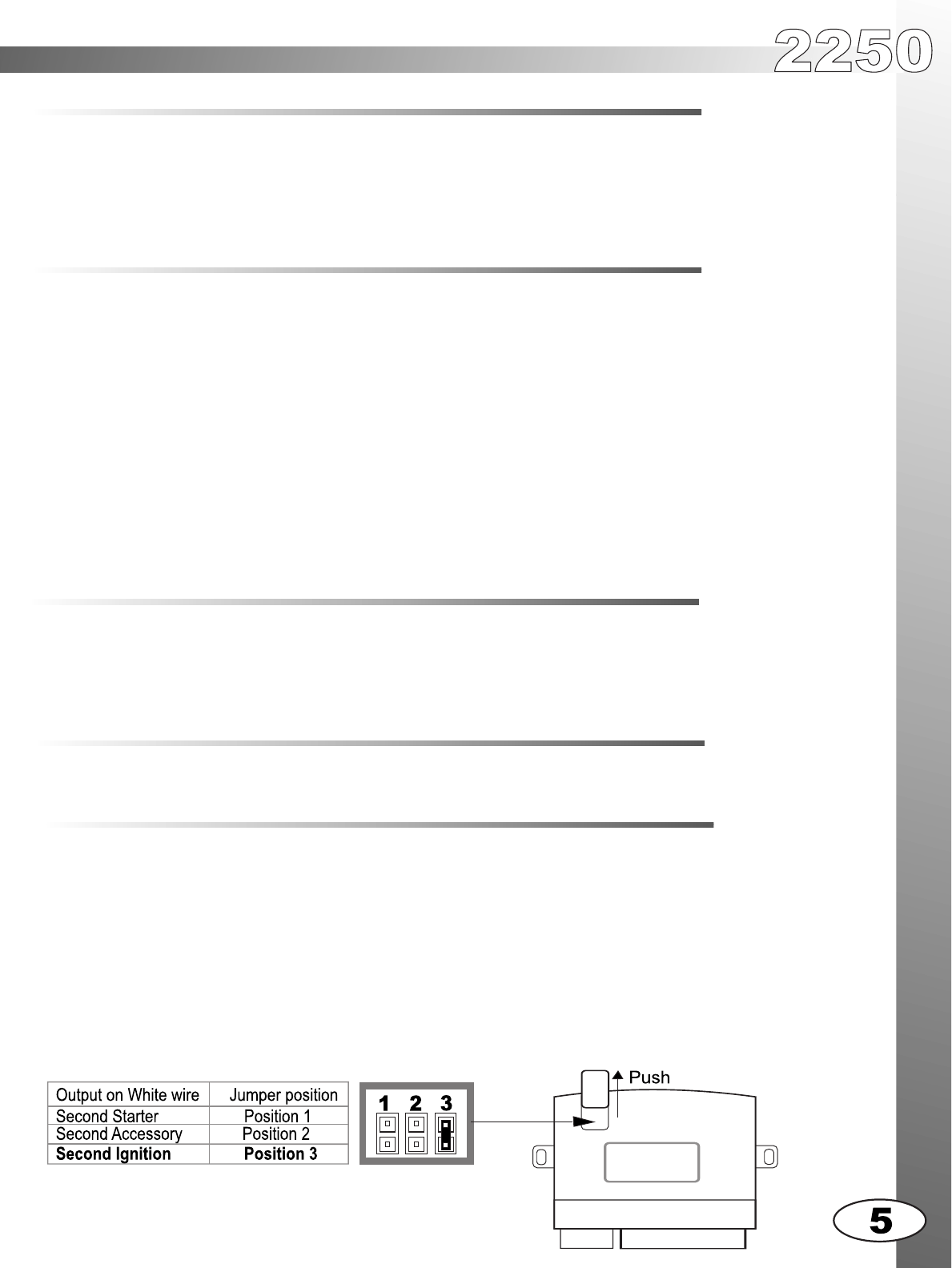
Jumper Selections
Antenna/ Program Button Connector.
The Antenna Must Be Connected Before the System will Operate.
Position One Second Starter Output On the White Wire From The 6-Pin Connector.
Position Two Second Accessory Output On The White Wire From The 6-Pin Connector.
Position Three Second Ignition* Output On The White Wire From The 6-Pin Connector.
* The Default Setting For The System Is Second Ignition Output.
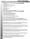
The jumpers control the output on the white wire from the six pin harness. To change the output of this wire, place the jumper in one
of the following positions
Note: The default setting is second ignition.
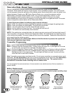
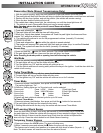
To change the jumper position you must first remove the access cover as shown in the diagram below.
The access cover will slide out of its position when pushed outwards from the center of the module.
Note: The center pin of this relay is low current and designed to power a voltage inverter. Do not use the center pin of
this connector to power relay packs. Doing so will damage the output. Always use a fused power source when installing
relays for keyless entry.
6 Pin Power Connector
INSTALLATION GUIDE
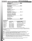
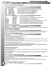
INSTALLATION TIPS
WIRING CONNECTIONS