


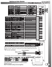
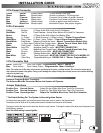
YELLOW
WHITE/BLUE
BLACK
BROWN
RED/WHITE
PURPLE
BLUE/WHITE
PINK
BLACK/WHITE
BLUE
WHITE
GREEN/WHITE
GREEN
ORANGE
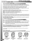
4 PIN
Blue
SIDE VIEW
ACTIVE RF ANTENNA
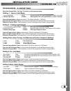
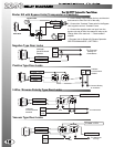
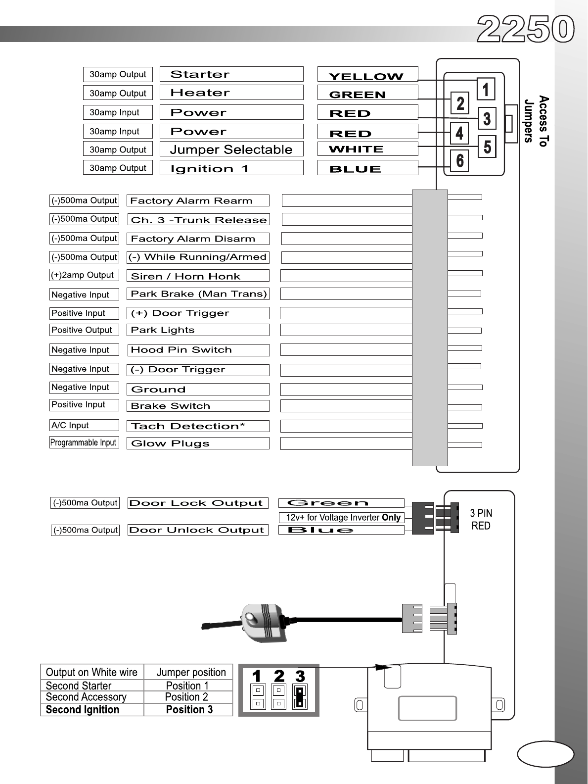
Jumpers
The jumpers control the output on the white wire from the
six pin harness. Place the jumpers in the above order to
change the output.
Note: The default setting is second ignition.
Status Led’s
Program Button
3
*This input is a optional connection for “TL” models. This input is programmable
and may need to be programmed for Tachless operation. See Page 11.
Note: The center pin of this connector is low current and designed to power a Voltage
Inverter. Do not use the center pin of this connector to power relay packs. Doing so will
damage the output. *Always use a fused power source when installing relays for keyless
entry.
**The antenna must be connected before the system will operate
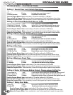
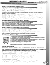
INSTALLATION GUIDE
WIRING DIAGRAM
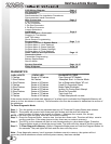
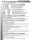
TABLE OF CONTENTS