


G
ELECTRICAL
G - 15
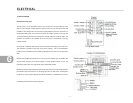
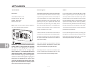
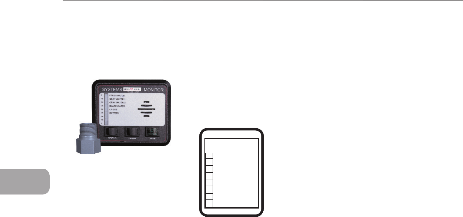
MONITOR PANEL
Micropulse Systems Monitor
CATCON PRODUCTS INC.
817-921-2188
techsupport@catconproducts.com
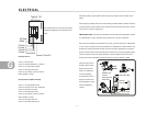
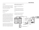
The MicroPulse System makes use of a single solid-
state sensor per tank. The MicroPulse sensor measures
the static (head) pressure at the bottom of the tank and
transmits this information to the MicroPulse System
Monitor. Knowing this pressure value, after a one-
time calibration has been performed, the MicroPulse
System will calculate and accurately display the tank
level in 1/8 increment.
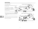
A single sensor is installed on the sidewall of each tank,
near the bottom, via a 3/4” female NPT spin-in thread.
The sensor is solid state, there are no moving parts to
wear or maintain. Because the principle of operation
does not involve any electrical current flow through the
tanks contents (conducted or induced), the nature of
the fluid in the tank is unimportant.
The monitor system has been calibrated at the factory
and should never need another calibration. If you feel
the system is not operating correctly, please contact
CATCON Products or a local Airstream dealer. The
following instructions are provided for qualified
service technicians.
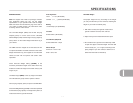
MICROPULSE SYSTEMS MONITOR
OPERATION INSTRUCTIONS
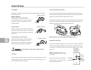
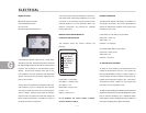
This example shows the monitor reporting the
following:
Fresh Water = 1/8 to Empty
Gray Water 1 = Empty to 5/8
Gray Water 2 = 3/4
Black Water = Empty to 5/8
LP Gas = 1/4
Battery = Empty to 5/8
On all diagrams the Letters R=Red, Y=Yellow,
G=Green, Blank=no LED lit.
NORMAL OPERATION
The MicroPulse Monitor will display the condition of
each system at all times. The tricolor LED beside the
system will indicate the condition of the system using
the following color code.
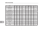
Fresh Water, LP Gas, Battery are as follows:
Green LED = 3/8 to Full
Yellow LED = 1/4
Red LED = 1/8 to Empty
Gray Water, Black Water are as follows:
Green LED = Empty to 5/8
Yellow LED = 3/4
Red LED = 7/8 to Full
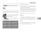
TO OBTAIN EXACT READING
To obtain an exact reading of all systems press and
release the status button one time. The monitor will
flash the LED beside the system it is about to report. It
will than display the exact condition of that system by
lighting the bar graph from Empty to Full. The monitor
will display the exact condition of each system and
then return to normal operation mode.
To obtain an exact reading of an individual system press and
release the status button until the LED beside the system
that you want the condition of is lit. Release the status
button and the monitor will display the exact condition of
that system by lighting the bar graph from Empty
Monitor Display
Fr
esh Water
Gray
Water 1
Gray
Water 2
Black Water
Batter
y
R
G
G
G
Y
Y
LP Gas