


Section
4
4-2
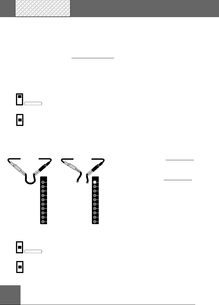
Continuity Checks
Test wiring, ground connections, switch operation, relay contacts, or similar.
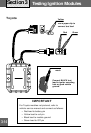
Important:
• Do continuity tests on
unpowered circuits only.
• Always make sure all connections are good. If necessary, scrape away
corrosion, paint, etc. at the contact points.
Warning: If working on-car, turn ignition key OFF and observe all safety
precautions (see page ii).
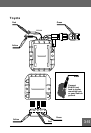
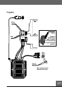
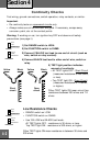
1) Set RANGE switch to HIGH.
2) Set FUNCTION switch to OHMS.
3) Connect YELLOW test lead to one end of circuit (such as
wire, switch or relay contact).
4) Connect BLACK test lead to other end of wire, switch or
relay.
RANGE
HIGH
LOW
POWER OFF
FUNCTION
VOLTS
OHMS
FREQUENCY
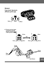
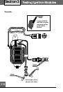
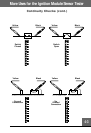
5) TEST light position indicates
amount of continuity.
• All TEST lights OFF -
Short Circuit
(measured resistance is 200 ohms,
or less).
• Top TEST light ON -
Open Circuit
(measured resistance is 7 Kohms,
or higher).
Other TEST lights ON mean circuit has
resistance between 200 ohms and 7 K
ohms.
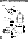
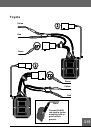
Low Resistance Checks
• RANGE switch on LOW.
• FUNCTION switch on OHMS.
• Use YELLOW and BLACK test leads.
All TEST lights OFF - resistance is 30 ohms, or less.
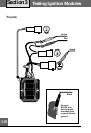
Top TEST light ON - resistance is 300 ohms, or higher.
Other TEST lights ON mean resistance is between 30 ohms and
300 ohms.
TEST
TEST
Yellow
Short
circuit
Yellow
Open
circuit
Black Black
FUNCTION
VOLTS
OHMS
FREQUENCY
RANGE
HIGH
LOW
POWER OFF