


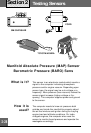

Testing Sensors
Section
2
2-32
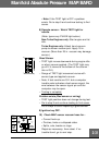
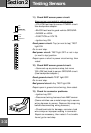
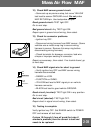
11) Check MAP sensor power circuit.
Keep sensor connected to vehicle wiring.
• YELLOW test lead to sensor POWER circuit.
Use backprobe adapter.
• BLACK test lead to good vehicle GROUND.
• RANGE on HIGH.
• FUNCTION on VOLTS.
• Ignition key ON.
Good power circuit:
Top (or next to top) TEST
light ON.
Go to next step.
Bad power circuit:
TEST light OFF or not in top
(or next to top) position.
Repair open or short in power circuit wiring, then
retest.
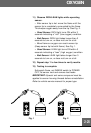
12) Check MAP sensor ground circuit.
• Same set-up as previous step, but move
YELLOW test lead to sensor GROUND circuit.
(Use backprobe adapter.)
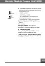
Good ground circuit:
TEST light OFF.
Go to next step.
Bad ground circuit:
Any TEST light ON.
Repair open in ground circuit wiring, then retest.
13) Check for connector problems.
• Ignition key OFF.
• Disconnect wiring harness from MAP sensor.
(Some vehicles use a metal snap ring to secure
wiring harness to sensor. Remove this snap ring
before disconnecting wiring harness.)
• Check terminals for damage, corrosion, bad
wire crimps or improper seating in connector.
Repair as necessary, then retest. If no trouble
found, go to next step.
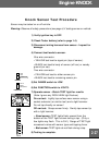
RANGE
HIGH
LOW
POWER OFF
FUNCTION
VOLTS
OHMS
FREQUENCY
TEST