


Section
1
1-2
3
TEST
Lights
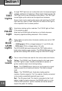
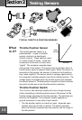
A single TEST light turns on to show the level of a measured signal
(voltage, resistance or frequency). When signal values are low, the
TEST light is off or near the bottom of the column. The TEST light
moves higher up the column as the signal level increases.
Sensor tests involve working the sensor and watching the TEST
light move up, down or flash. Note that the motion of the light is
more important than its actual position.
Used when testing ignition modules. The PULSE light will flash
if the module is good.
Note that the PULSE light will also be on (or flash) whenever
frequency signals are being measured - this is normal.
4
PULSE
Light
RICH/
LEAN
Lights
5
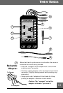
These lights are active when the tester switches are set to LOW
VOLTS only.
• LEAN (green): ON for voltages between 0.1 and 0.59 volts.
• RICH (red): ON for voltages above 0.6 volts.
The RICH/LEAN lights work along with the TEST lights and are
helpful when testing oxygen sensors. The RICH/LEAN lights may be
ignored when testing other sensors using the LOW VOLTS range.
6
Test
Leads
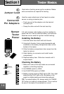
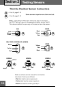
Two or more of these are used for the various tests and checks.
Yellow - The SIGNAL lead. Signals probed by this lead cause
the TEST lights to react. Usually connected to a sensor or
ignition module output circuit during testing.
Black - The COMMON lead. Used as a circuit ground or signal
reference point for all tests and checks. This lead is always
used.
Green - The TRIGGER lead. Used when testing ignition
modules. Sends a signal to “fire” the module. Usually connected
to the module crankshaft/camshaft input circuit.
Red - The 9V power lead. This lead is connected to the 9 volt
battery inside the tester whenever the RANGE switch is in the
LOW or HIGH positions. Ignition modules and some sensors
require this power for testing.
6