


Crankshaft/Camshaft Position
2-47
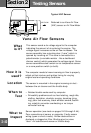
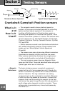
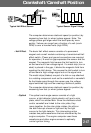
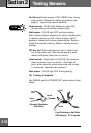
The optical crank angle sensor consists of a light
source, a light detector (photo-electric cell) and a rotor
plate, which is a slotted disk. Since the distributor shaft
and/or camshaft are linked to the rotor plate, they
move together. As the rotor plate rotates, the slits on
the disk interrupt a beam or light sent by the light
source to the light detector. This interrupting action
creates two pulse waveforms that are monitored by the
engine computer. The engine computer uses these
waveforms and other engine sensors to optimally
control ignition timing.
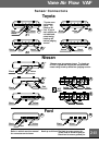
• Optical
SHUTTER
POWER
GROUND
SIGNAL
MAGNET
HALL
SWITCH
HIGH
SIGNAL
VOLTAGE
LOW
ROTATION
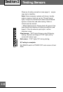
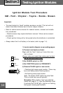
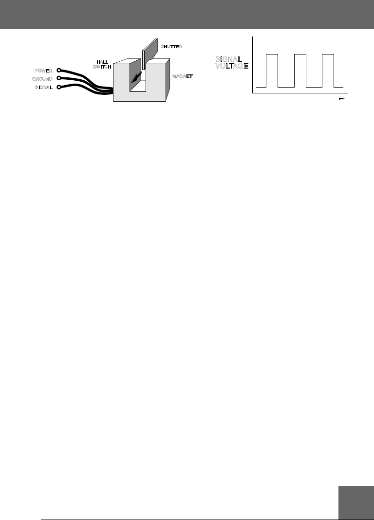
• Hall Effect The basic Hall effect sensor consists of a permanent
magnet and a small module containing a transistorized Hall
effect switch. (Power and ground connections are required
for operation.) A small air gap separates the sensor and the
magnet. The magnetic field causes the Hall switch to turn
on and send out a low voltage signal. If a metal strip (iron or
steel) is placed in the gap, it blocks the magnetic field from
reaching the Hall device. This causes the Hall switch to turn
off and send a high voltage signal out on the signal wire.
The metal strips (blades) are part of a disk or cup attached
to a rotating component such as the crankshaft or camshaft.
As the blades pass through the sensor gap, the voltage
signal switches high and low creating a series of pulses.
The computer determines rotational speed (or position) by
measuring how fast (or when) pulses appear.
The computer determines rotational speed (or position) by
measuring how fast (or when) pulses appear. Note: The
voltage pulses get larger when the teeth pass by more
quickly. Values can range from a fraction of a volt (crank
RPM) to over a hundred volts (high RPM).
Typical Hall Effect Sensor Typical Sensor Signal Voltage