


7-34
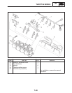
THROTTLE BODIES
FI
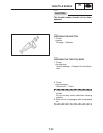
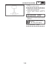
NOTE:
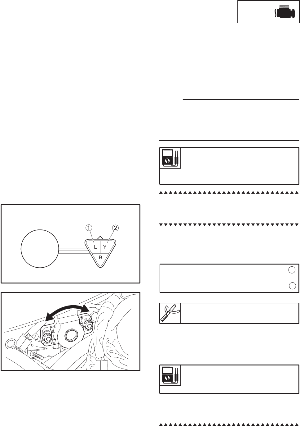
Tester positive probe ! blue terminal
Tester negative probe !
yellow terminal
1
2
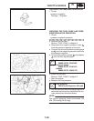
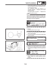
f. While slowly opening the throttle, check that
the throttle position sensor resistance is with-
in the specified range.
The resistance does not change or it
changes abruptly ! Replace the throttle
position sensor.
The slot is worn or broken ! Replace the
throttle position sensor.
Check mainly that the resistance changes grad-
ually when turning the throttle, since the read-
ings (from closed to wide-open throttle) may dif-
fer slightly from those specified.
Throttle position sensor
resistance
0 X 5 " 1.5 kΩ at 20_C (68_F)
(yellow - black)
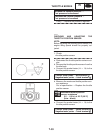
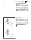
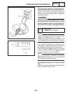
2. Adjust:
Sthrottle position sensor angle
a. Connect the throttle position sensor coupler
to the wire harness.
b. Connect the digital circuit tester to the throttle
position sensor.
Digital circuit tester
90890-03174
c. Measure the throttle position sensor voltage.
d. Adjust the throttle position sensor angle so
the measured voltage is within the specified
range.
Throttle position sensor voltage
0.63 X 0.73 V
(yellow – blue)
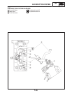
g. After adjusting the throttle position sensor
angle, tighten the throttle position sensor
screws.