


Troubleshooting
4–4
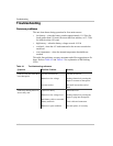
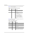
Table 4-2 explains the blinking pattern of the AC input LED when the
inverter is connected to shorepower.
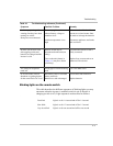
Table 4-3 explains the inverter LED flashing pattern when the unit is in
invert mode or in charge mode.
Table 4-2 Interpreting AC input LED blink patterns
Inverter
LED AC input LED Condition
Off ON Connected to shorepower within 100
to 130 Vac range and battery charger is
operational
Off Very slow blink • Delay on transfer from the inverter
to shorepower
• AC power is not in range (outside
100 to 130 Vac range)
• Battery is not being charged. AC
output load may be too great
• Extension cord to shorepower may
be too long or not of sufficient
conductor size, resulting in voltage
drop
Table 4-3 Inverter LED blink patterns
Unit in invert
mode
Unit in charge
mode Condition
Slow blink N/A Low battery
Fast blink Fast blink High battery
Fast blink Slow blink Unit over temperature and has shut down
Fast blink Slow blink Ambient temperature too high and unit
has shut down
Slow blink N/A Over current
Very slow blink N/A Auto shutdown. Inverter has shut down
because no load has been detected in 24
hours or the load is too small to detect