


Operation
2–10
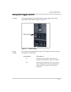
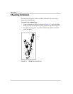
Switch LEDs The LEDs provide information about the operating state of the
inverter/charger. Under normal operating conditions the lights will behave
like this:
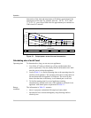
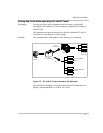
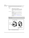
Figure 2-4 Inverter/charger switch positions
AC LED: Illuminated when there is shorepower.
Blinks slowly (once per second) when first connecting
to shorepower then lights steadily or it will continue to
blink if the AC voltage is not within range (100 V to
130 V).
Inverter LED: Illuminated when the unit is inverting and there is no
shorepower.
If the LED is blinking once every two seconds (very
slow blink), it means the unit has shut down to avoid
draining the batteries.
A fast-blinking Inverter LED light indicates a unit
fault. Refer to Chapter 4, “Troubleshooting” for more
information.
Note: Some switches may also have a center position. The center position also
enables the inverter.
AC LED
Inverter disabled (off)
when switch pushed up
Inverter enabled (on)
when switch is pushed
down
Inverter LED