


USSC Page 15
--
--
--
--
--
--
--
1.
2.
3.
4.
Relay...electrical switching device,
Rheostat...current (voltage) reducer increases or
decreases draft fan R.P.M.
Distribution Capacitor: Reduces amps required
to activate distribution fan.
Transformer: Reduces voltage 110 volts to 24 volts
for thermostat usage. Generally hums a bit.
170 degree limit disk...breaks off electrical current
to the draft fan at 170 degrees
(2) adjustable140 degree limit disc...closes at set
temperature to operate distribution blowers.
Thermodisc’s range is 95-140. (see illustration for
location)
Draft fan...small fan that activates fire, increasing
fire temperature.
Wall mounted thermostat requests heat...electrical
contact occurs.
Current is sent through relay, rheostat, 170 degrees
thermo limit disk to activate draft fan.
Upon firebox temperature rise due to air from draft
fan, current passes thru the top/right thermodisc
to activate the left distribution fan. The factory
seting is approximately 120 degrees air tempera-
ture, 500 CFM of air at 120 degrees.
Should firebox temperature air reach 140 degrees,
current is directed thru the bottom/right
thermodisc to activate the second fan for 1,000
CFM of air.
Both blowers will continue to run until air tempera-
ture drops approx. 20 degrees below the set point
on the thermodisc.
Your new furnace is now completely assembled and
ready to be installed. Make sure you followed the
sections on installation in the front of this manual.
OPERATION OF YOUR NEW SOILD
FUEL BURNING FURNACE.
Check that your draft blower is in working order be-
fore lighting a fire (cover setting 20% open).
Do this by turning the room thermostat to a high tem-
perature so that the draft blower turns on, then turn
the thermostat back to proper setting thus turning the
draft air blower off. Should draft blower not func-
tion, check to see if rheostat setting is on.
NOW PROCEED WITH LIGHTING
A FIRE.
The above is somewhat basic, however, it's offered
so you can understand your furnaces electrical func-
tions and enjoy it more.
CAUTION:
Never use chemicals or fluids such as gasoline,
charcoal lighter fluid, drain oil or kerosene to
light a fire in your furnace. This would be like
checking the level of gas in your car with a
lighted match.
10 BASIC FUNCTIONS OF ELECTRICAL SYSTEM
1.
2.
3.
4.
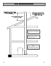
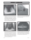
Pull bypass damper out (opens up flue hole).
Make sure your flue pipe damper is open. Place
several pieces of crumpled paper in the center of
your firebox. In a crisscross pattern, place a couple
of handfuls of dry kindling wood, then several small
dry pieces of firewood.
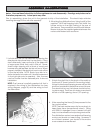
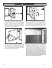
Ignite the paper and close the door. Do not at-
tempt to open the door immediately after ignit-
ing the fire. There could be a flame flash out.
It will take a few minutes for the fire to establish
itself. Once you have some good red hot burn-
ing coals, add larger pieces of wood. All Chim-
neys and hookups act differently. After a while,
you will find out how your unit works best for start-
ing.
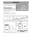
CONTROL BOCONTROL BO
CONTROL BOCONTROL BO
CONTROL BO
X & ELECTRICAL COMPONENTX & ELECTRICAL COMPONENT
X & ELECTRICAL COMPONENTX & ELECTRICAL COMPONENT
X & ELECTRICAL COMPONENT
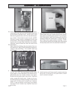
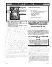
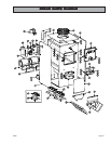
ELECTRICAL COMPONENTS
Wall Thermostat
*(2) 140 degree Adjustable Thermo Disk
*(1)170 degree Thermo Limit Disk
*(1)Relay Transformer
(2) Air Distribution Fan
(1)Draft, Fan
* Control Box Components
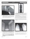
170 degree
limit disc
140 degree
adjustable disc.
(Left Dist. Blower)
140 degree
adjustable disc.
(Right Dist. Blower)