


Page 10 USSC
NOTE: Your furnace may come partially pre-assembled, but in the case that it is not, follow the instructions
below. Also use these instructions for future maintenance and disassembly. Drawings and photos are for
illustration purposes only. Actual parts may differ.
Prior to assembling, place the unit in the general vicinity of the installation. This should help minimize
handling damage to the unit after assembly.
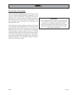
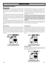
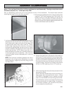
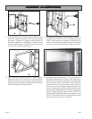
1. Unit side shrouds can be assemble by slipping the
side shrouds into place from the top down. If they
don't slide easily, open up the lip of the sides with
a large screw driver then add a little oil. Some-
times a slight tapping with a block of wood and
hammer may be required, but do not force. When
properly installed, the electrical knock-outs will be
at the top left side. NOTE: Should you wish to in-
stall a domestic hot water coil, it should be secured
to the right side prior to assembly. Also, the rear
cast iron baffle must be fastened prior to shroud
installation.
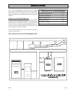
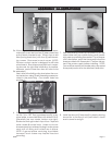
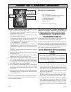
NOTE: The furnace is partially prewired all that is
required is the wiring of the distribution fan (see
wiring diagram, page 18) and the wiring to wall
the thermostat.
4. After mounting the three (3) fans proceed to the
fan control center.
NOTE: The best maintenance for fan motors is to
keep them clean (exceptionally clean). Oiling
with 20W N. detergent once a season will also
help, but cleanliness is what prolongs motors life.
The distribution motors have sealed ball bearing
motors and should not need oiling. However, if
an oil tube is present, you should oil the motors
once a season as mentioned.
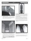
Attaching the distribution fans. Using four(4) of the
supplied 1/4-20 self-tapping bolts, first install the
blower motor on the right looking at the rear of
the furnace. Then proceed to mount the left blower.
Be sure to place the supplied gaskets between the
motors and firebox back as shown.
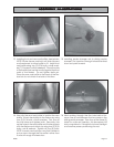
Attach the draft fan to the back of the weld on
the throat (2" throat hole with 3 mounting holes).
It's best to use the self tapping screws without the
draft fan to establish threads then mount blower.
The electrical box on the blower should be fac-
ing downward. Draft fan air intake cover should
be set at a 20% opening, about 1/2" opening.
3.
ASSEMBLASSEMBL
ASSEMBLASSEMBL
ASSEMBL
Y ILLY ILL
Y ILLY ILL
Y ILL
USTRAUSTRA
USTRAUSTRA
USTRA
TIONSTIONS
TIONSTIONS
TIONS
2.