


1716
Application Notes
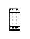
When measuring resistance of a motor,
make sure the power is disconnected prior
to testing.
Set up the meter following steps under
“Measurement Procedure” on page 17, and
then proceed with the following:
• Connect the red test lead to one power
input line of the motor and the black
test lead to the other power input line
of the motor. In most applications if
the reading is OFL, the motor winding
is open.
• Connect the red test lead to the frame
of the motor and the black test lead to
the winding. In most applications if a
reading of 0 Ohms is displayed, the
winding is shorted to the motor frame
(ground).
e. Measuring Resistance
WARNING!
Do not attempt to make resistance measurements with
circuit energized. For best results, remove the resistor
completely from the circuit before attempting to
measure it.
NOTE:
To make accurate low ohm measurements, short the ends of
test leads together and record resistance reading. Deduct
this value from actual readings.
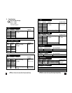
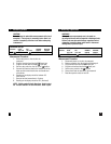
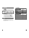
Instrument set-up:
FUNCTION BLACK RED MINIMUM MAXIMUM
TEST LEAD TEST LEAD READING READING
OHM COM VΩ 0.1Ω 19.99MΩ
Measurement Procedure:
1. Disconnect power to circuit to be measured.
2. Plug black test lead into the COM input jack.
3. Plug red test lead into the VΩ input jack.
4. Set the rotary switch on the 135 to the desired range
in the OHM function depending on the voltage to be
measured.
5. Connect test leads to circuit to be measured.
6. Read the resistance value on the 135.