


1918
f. Measuring Diodes
CAUTION!
Do not attempt to make diode measurements with circuit
energized. The only way to accurately test a diode is to
remove it completely from the circuit before attempting
to measure it.
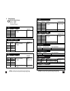
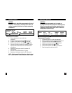
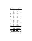
Instrument set-up:
FUNCTION BLACK RED MINIMUM MAXIMUM
TEST LEAD TEST LEAD READING READING
OHM( ) COM VΩ 0.001V 2.000V
Measurement Procedure:
1. Disconnect power to the circuit to be
measured.
2. Plug the black test lead into the COM input jack.
3. Plug the red test lead into the VΩ input jack.
4. Set the rotary switch on the 135 to the position.
5. Connect the black test lead to the banded end of the
diode and the red test lead to the non-banded end
of the diode.
6. Reading on the display should be between 0.3
and 0.8 volts.
7. Reverse test lead connections in 5 above.
8. Reading on the display should be OFL (Overload).
NOTE: If diode reads 0 in both directions, diode is short-
ed. If diode reads OFL in both directions, diode is open.
g. Measuring Capacitance
WARNING!
All capacitance measurements are to be made on
de-energized circuits with all capacitors discharged only.
Failure to de-energize and discharge capacitors before
attempting to measure them could result in instrument
damage and/or personal injury.
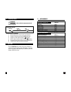
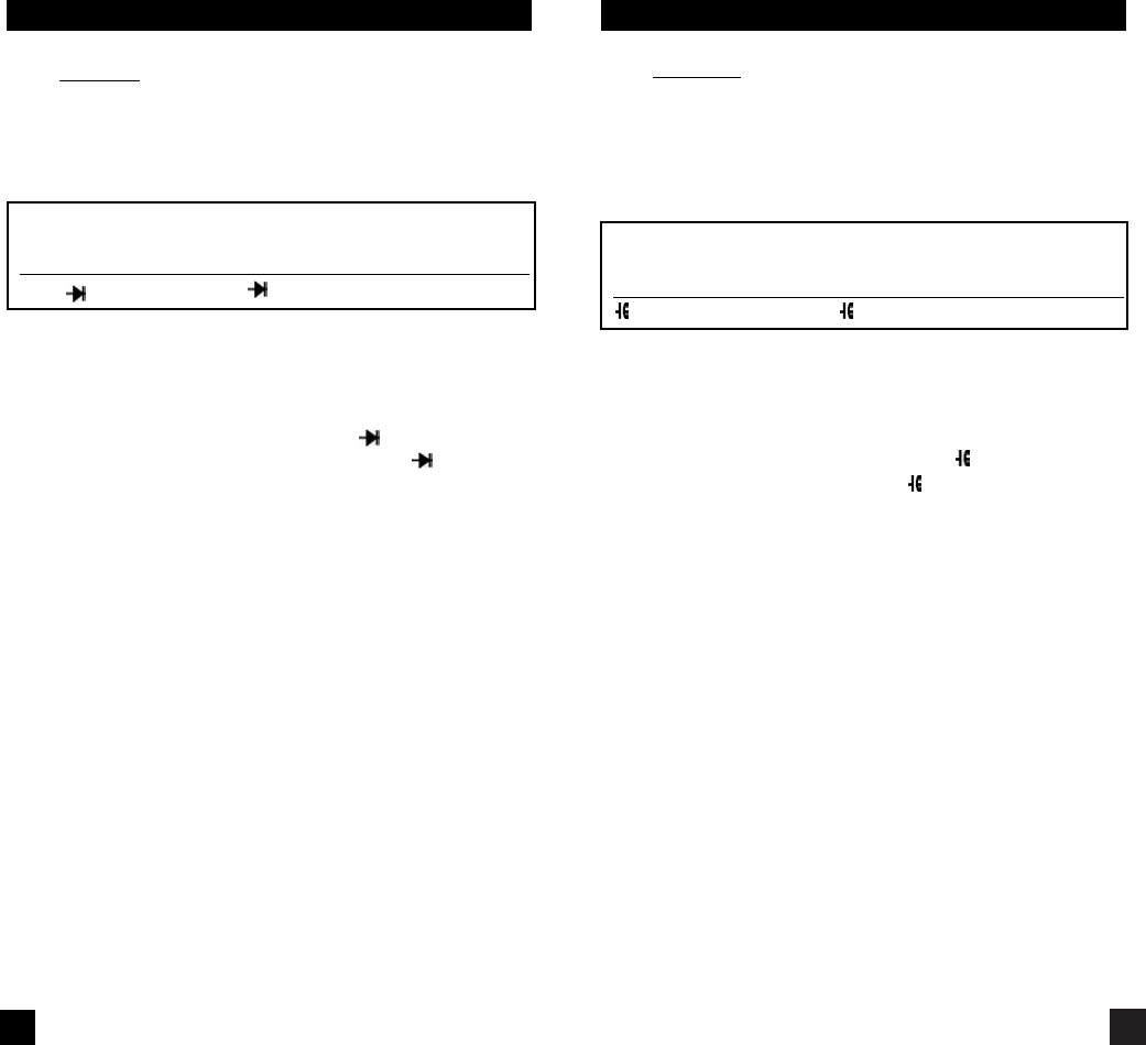
Instrument set-up:
FUNCTION BLACK RED MINIMUM MAXIMUM
TEST LEAD TEST LEAD READING READING
COM VΩ 0.01µF 20000µF
Measurement Procedure:
1. Disconnect power to circuit to be measured.
2. Remove capacitor from the circuit and discharge it.
3. Plug black test lead into the COM input jack.
4. Plug the red test lead into the VΩ input jack.
5. Set the rotary switch to the function.
6. Connect test leads to capacitor to be measured.
7. Read the capacitor value on the LCD.