


1514
d. Measuring AC Amps
CAUTION!
Do not attempt to make a current measurement with
the test leads connected in parallel with the circuit to be
tested. Test leads must be connected in series with
the circuit.
W
ARNING!
Do not attempt to make a current measurement of
circuits with more than 600V present. Instrument
damage and/or personal injury may result.
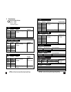
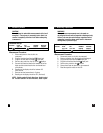
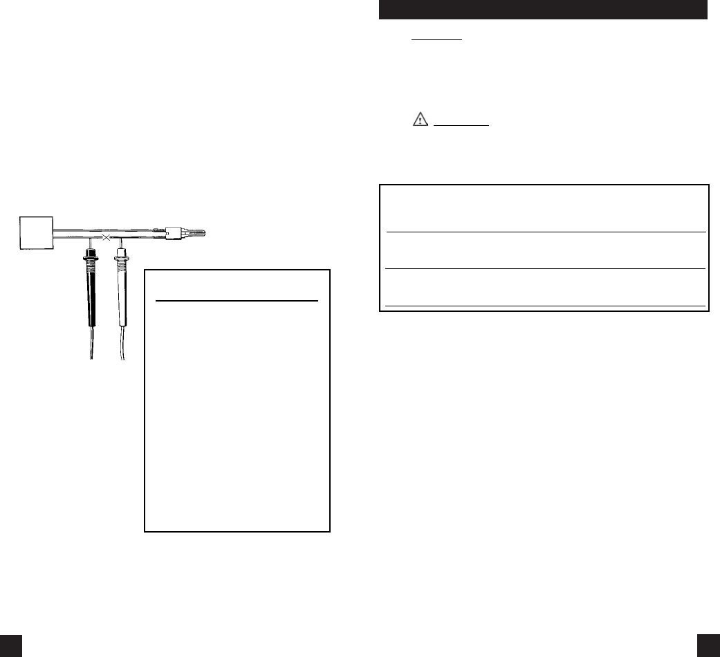
Instrument set-up:
FUNCTION BLACK RED MINIMUM MAXIMUM
TEST LEAD TEST LEAD READING READING
ACA COM mAµA 0.1µA 1.999A
(up to 2A range)
ACA COM A 0.01A 10.00A
(10A range only)
Measurement Procedure:
1. Disconnect power to circuit to be measured.
2. Plug black test lead into the COM input jack.
3. Plug red test lead into mAµA or A input jack
depending on value of current to be measured.
4. Set the rotary switch on the 135 to the desired range
in the ACA function depending on the current to be
measured and the input jack the red test lead is
inserted into.
5. Connect the test leads in series to the
circuit to be measured.
6. Reconnect power to circuit to be measured.
7. Read the current on the 135.
c. Measuring DC Amps (cont.)
Measurement Procedure:
1. Disconnect power to circuit to be measured.
2. Plug black test lead into the COM input jack.
3. Plug red test lead into mAµA or A input jack
depending on value of current to be measured.
4. Set the rotary switch on the 135 to the desired range
in the DCA function depending on the current to be
measured and the input jack the red test lead is
inserted into.
5. Connect test leads in series to circuit to be measured.
6. Reconnect power to circuit to be measured.
7. Read the current on the 135.
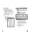
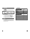
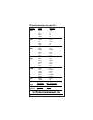
Application Notes
When measuring the DC current
of a flame controller, follow the
steps under “Measurement
Procedure” above and then
proceed with the following:
• Set up the meter for
making a µA measurement.
• Connect the meter to the
flame controller lead by
opening the circuit and
inserting the leads in series
with the circuit as shown in
the picture above.