


2120
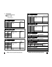
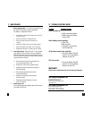
E. ACCESSORIES*
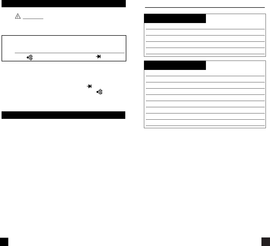
Standard Accessories Part No.
9V Battery A009
Fuse, 2 Amp A102
Fuse, 10 Amp A110
Test Lead Set A050
Rubber Boot (135 only) A101
Optional Accessories Part No.
Deluxe Test Lead Set SDK1C
IEC 1010 Deluxe Test Lead Kit TLS2000B
Temperature Adapter A301
Boot Hook A103
Soft Carrying Case A100
Screw-on Alligator Clips A150
CO Attachment A701
CO Attachment w/Alarm A702
CO Attachment w/zero adjust A711
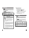
h. Continuity Buzzer
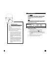
W
ARNING!
Do not attempt to make continuity measurements with
circuit energized.
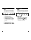
Instrument set-up:
FUNCTION BLACK RED
TEST LEAD TEST LEAD
OHM( ) COM VΩ
Measurement Procedure:
1. Disconnect power to the circuit to be measured.
2. Plug the black test lead into the COM input jack.
3. Plug the red test lead into the V input jack.
4. Set the rotary switch on the 135 to the position.
5. Connect the test leads to the circuit to be measured.
6. Listen for the buzzer to confirm continuity.
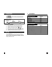
i. Data Hold
Press the DATA-H button at any time on any function or
range to freeze the reading on the LCD display. This func-
tion is very useful when measuring in locations where the
display is difficult to read.