730 Bubbler Module
Section 3 Installation Methods
3-3
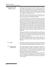
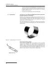
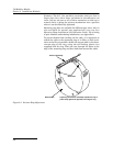
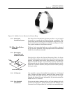
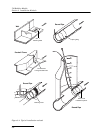
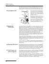
Route the vinyl bubble line away from the carrier and along the
spring ring’s edge with holes. Secure the line in position by
placing plastic ties through the holes and then locking them
around the line. To prevent debris from collecting, attach the line
so that it offers as little resistance to the flow as possible. Avoid
loops or slack sections. Attach it neatly and closely to the spring
ring.
Installing the Spring Ring:
After the bubble line and carrier have been attached to the
spring ring, the actual installation procedure is fairly simple.
First, lower the spring ring assembly into the area of the pipe.
Next, grasp the spring ring and compress it into a tight circle.
Then push the ring up into the pipe the desired distance.
When you have the ring positioned, release the ring, allowing it
to expand outward. It may be necessary to rotate the ring to
position the bubble line outlet in the bottom center of the pipe.
This completes the installation.
Under conditions of high velocity (greater than five feet per
second or 1.5 meters per second), the spring ring may not have
sufficient outward force to keep it tight against the pipe. The flow
could lift the ring off the bottom of the pipe, or even carry it
downstream.
This problem is more prevalent in the larger diameter pipes (10,
12, and 15 inch) and in pipes with a smooth inner surface
(plastic, for example). If any of these conditions are present, or if
movement of the spring ring is detected or suspected, you must
anchor the ring in place. You can do this by shooting studs
through the ring into the pipe or by other appropriate means. In
some cases, it may be sufficient to increase the outward force of
the ring by bending it into a less rounded shape.
3.1.3 Scissors Rings Consult your Isco Mounting Rings instruction manual for
detailed hardware information.
For pipes larger than 15" in diameter, Teledyne Isco offers the
adjustable Scissors Ring (also known as the Universal Mounting
Ring). This device consists of two or more metal strips that lock
together with tabs to form a single assembly. There is a base
section where the sensors are mounted, one or more extension
sections (usually), and a scissors section at the top that expands
the entire assembly and tightens it inside the pipe. The scissors
mechanism includes a long screw that increases the width as it is
tightened.
The assembled rings fit pipe diameters from 16" to 80". Secure
the unit in place by tightening the scissors mechanism with a
5
/8"
socket wrench or other suitable tool. Ring sections are .040" thick
half-hard 301 stainless steel sheet. All other parts are also
stainless steel, except for the plastic cable ties in the hardware
kit.
Each extension, 1, 2, 3, and 4, adds 9.0", 21.5", 31.5", or 41.5",
respectively, to the circumference of the ring. Used alone, the
base section fits pipe that is approximately 16" to 18" in
Spring Ring Preparation
F
l
o
w
Plastic
Ties


