


730 Bubbler Module
Section 1 Introduction
1-3
1.6 General Mounting
Considerations for the
Bubbler
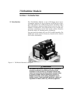
This section contains some general information regarding the
installation of the 730 module. More detailed installation infor-
mation can be found in Section 3 Installation Methods.
1.6.1 Line Length A standard 25 foot (7.6 m) length of
1
/8" (0.32 cm) ID vinyl line is
shipped with the module. We recommend that you do not use
lengths longer than 25 feet. Please consult with the factory if
your installation requires a nonstandard setup.
Cut the bubble line to the shortest usable length. This will min-
imize friction head effects in the line and also will reduce the
amount of line exposed to cuts, kinks, etc. This will also improve
the response time to changing levels and make the purge more
effective.
The bubble line should be routed and secured so that it does not
disturb the flow. Do not kink the tubing or restrict the airflow by
over-tightening the mounting hardware.
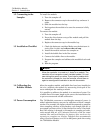
1.6.2 Attach the Bubble Line
to the Module
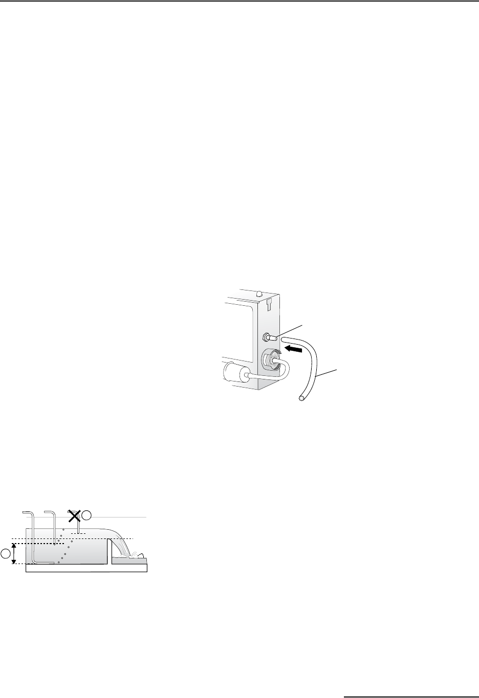
The vinyl bubble line attaches directly to the barbed fitting.
Simply push the tubing over the fitting.
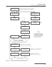
1.6.3 Bubble Line Position in
the Stream
The bubble line outlet does not need to be at the bottom of the
stream. In fact, positioning the bubble line outlet above the
bottom can be beneficial if the stream carries large amounts of
solids or is subject to silting.
The simplest installation method attaches the bubble line to the
side of the flow stream with the bubble line outlet positioned
below the lowest expected level.
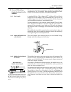
To measure the liquid level down to the actual “zero” level of the
primary device, Teledyne Isco recommends placing the bubble
line outlet at least 1 to 2 inches (2.5 to 5.1 cm) below the
primary device “zero” level to avoid measurement failures when
the liquid level is even with the outlet. The module cannot accu-
rately measure levels that are even with or below the bubble line
outlet.
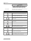
Barbed Fitting
Vinyl Bubble Line
A
B
A. The recommended depth ranges from
the bottom to 1 inch below the zero level.
B. This position would be unable to
measure low levels through the primary
device.
Recommen
d
e
d
Bubble Outlet Depth
Zero