


140-072011 200/202 Series Page 9 of 24
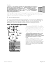
2.4. Mechanical Connections
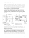
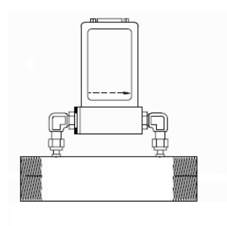
2.4.1. Standard Configuration
The flow meter may be mounted in any position as long as the direction of gas flow through the
instrument follows the arrow marked on the bottom of the flow meter case label. The preferred
orientation is with the inlet and outlet fittings in a horizontal plane (if operating with a dense gas or at high
pressures the instrument must be installed horizontally). When mounted in a different orientation the
instrument should be re-zeroed at zero flow with the system pressurized to the expected operating
pressure.
The smallest of the internal passageways in the HFM-200/HFC-202 series is the diameter of the sensor
tube, which is 0.0125” (0.31 mm), so the instrument requires adequate filtering of the gas supply to
prevent blockage or clogging of the tube.
The pressure regulator and the plumbing upstream must be of sufficient size to minimize changes in the
upstream pressure. When switching from full flow to zero flow, the inlet pressure of the instrument
should rise to no more that 30% above the inlet pressure at full flow. In general, high capacity regulators
and large internal diameter plumbing help to make the system more stable. The pressure drop between
the regulator and the instrument due to line resistance should be minimized. The differential pressure
across a meter should be less than 6” of H
2
O at maximum flow. Controllers may have much higher
differential pressures depending upon the size of the installed orifice.
There are two 8-32 threaded holes, located on the bottom of the base that can be used to secure it to a
mounting bracket, if desired (screws provided). Other holes for special mounting can be added to the
end cap as desired.
The standard inlet and outlet fittings for the 200/202 are 0.25” and 0.125” Swagelok (optional VCR or
VCO fittings). The O-rings for the end cap and the sensor are Viton (optional Kalrez or Neoprene). It is
suggested that all connections be checked for leaks after installation. This can be done by pressurizing the
instrument (do not exceed 500 psig unless the Flowmeter is specifically rated for higher pressures) and
applying a diluted soap solution to the flow connections.
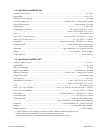
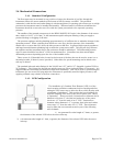
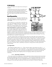
2.4.2. LFE Configuration
The installation of a Laminar Flow Element (LFE) in a flow
circuit requires sufficient conductance before entering and after
exiting the LFE sensor taps to allow the flow to fully develop with
a minimum of turbulence. This provides the best conditions for
accurate sampling of the flow by the sensor branch (See Theory
of Operation). Please note that, for laminar flow elements whose
diameter is less than 3”, the inlet and outlet taps of the sensor
circuit are 1.5” from the ends of an 8” LFE. Laminar flow
elements whose diameter is 3” or greater, have inlets and outlets
sensor taps 2.5” from the ends of a 10” LFE. These distances
may be taken into account and treated as part of the following
rule-of-thumb:
1) an upstream flow tube length of 5 times, or greater,
the diameter of the selected LFE before the sensor inlet tap.
2) a downstream tube length of 1 time, or greater, the diameter of the selected LFE after the sensor
inlet tap.